Home › Electrical Engineering Forum › General Discussion › Difference Between Series & Parallel Transformer
- This topic has 1 reply, 2 voices, and was last updated 7 years, 9 months ago by
pradeepkumar.
-
AuthorPosts
-
2013/06/21 at 2:43 pm #11027
admin
KeymasterRight after the article “Behavior of Transformer on Loading“, let’s read the 5th part of Nasir’s tutorial on transformers. You want your articles, works, reviews or tutorials be published in our blog? Simply send us a mail!
We know that a transformer generates its current output with the help of two windings, namely Primary and secondary windings. The primary coil of the transformer is always connected to the alternating power supply, as it is the only method of supplying power to the transformer, by connecting the power supply in parallel with the two free ends of the primary windings. The current produced is then transferred to the secondary winding by Faraday’s law of Mutual Induction.
Since a transformer can have more than one primary winding or secondary windings as well, so if two or more coils exist at any terminal, then they can be connected with each other in two basic ways. These two ways for connecting the two or more windings with each other are:
- Series Connections
- Parallel Connections
Series Connection of windings
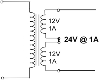
The secondary windings of a transformer, connected in series are shown below:
As we know that the voltage is divided in series whereas the current remains the same. So if there are more than one primary winding, then the supply voltage gets divided equally in all the windings at the input terminal but the current remains the same.
Now at the secondary terminal, if we are using two windings rated at 12 V each, as shown in the figure above, then we get a total of 12 V + 12 V = 24 V at the output terminal, which means that the voltage has added up. The same amount of current will flow through each of the windings, which is 1 A for each in this case, and hence the total current at the output is also equal to 1 A.
From this we can conclude that, if we want to get twice the voltage at the output, we can connect two secondary windings in series and so on, provided that the current will remain constant.
Parallel Connection of Windings
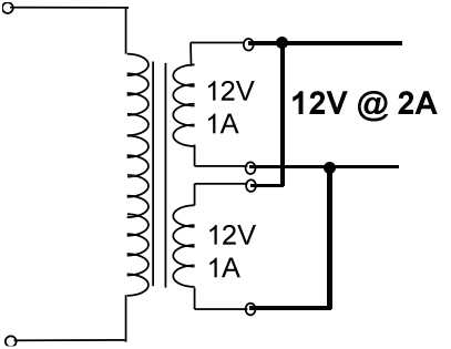
The secondary windings of a transformer, connected in parallel are shown below:
As we know that the current in a parallel combination divides or adds up, so in this case as well, if the primary windings would also have been connected in a parallel combination, then the current supplied by the source would have been divided, but at the output terminal, as we see that both the secondary windings which have been connected in parallel are rated at 1 A each, so the current will add up here, and as there are two windings, so it adds up like 1 A + 1 A = 2 A total.
Since the voltage remains the same, so the voltage drop across the output terminal will be the same as that on each of the windings of the transformer and the output above will be rated as 12 V, 2 A transformers.
If we use a dual voltage transformer, then only the readings of the current and voltage will be changed accordingly, but the principle that the voltage remains constant in parallel combination and the current adds up at the output, remains the same.
Moreover, other than these two configurations, other types of connections are also available, like driving two independent outputs by two individual secondary coils of a transformer, such that both of them have no inter connection.
One thing that should be taken care of is that while connecting two windings with each other, their phase relationships should be kept in mind and the connections should be made accordingly. If the terminals with opposite phase relationships are connected with each other, they will cancel the effect of each other’s magnetic flux, and hence we won’t get any output. So in order to get the desired output, only the terminals with the same phase relationships should be connected with each other.
In the coming post, we will discuss a special type of transformer named as Centered Tapped Transformer. It is designed to provide two types of voltages at the secondary side and has unique applications. We will discuss its principal, working and applications in the coming post.
Nasir.
2017/06/28 at 6:38 am #17776pradeepkumar
ParticipantThanks for sharing good information about power transformer.
-
AuthorPosts
- You must be logged in to reply to this topic.

