Here is the 4th part of Nasir’s tutorial on transformers. The 3d one was Losses in a transformer. If you want to write for the blog just like Nasir, don’t hesitate and send us a mail.
What is loading?
A load is a part of the circuit which consumes electrical energy or power and converts it into some other form like heat of some external mechanical work or electrical energy. Similarly, when an external circuit is attached to the secondary coil of the transformer, so that it consumes some of the electrical energy or power contributed by the secondary coil, then the transformer is said to be in a loading condition.
Current can only flow through the circuit if it is closed, i.e. only if the secondary coil has a closed circuit attached to it, called the load, only then the current will flow through it. The load on a transformer can be of several types:
- Resistive Load
- Capacitive Load
- Inductive Load
- Or a Combination of above types
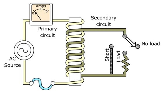
No Load Behavior of a Transformer
When the secondary coil of the transformer is not connected to any external circuit or both its two ends are open, then the transformer is said to be in a no load condition. In this case, when the current is supplied to the primary coil of the transformer through an external alternating source, then this current is used for magnetizing the core of the transformer, but in actual is not exactly equal to the magnetization current. This is due to the fact that the current which is supplied to the primary coil at no load condition has two components.
One is the magnetizing component which is merely utilized for the production of the alternating magnetic flux in the core, while the other one is the energy supplying component which is used for the compensation of the core losses of the transformer.
These two components can be vector ally represented as follows:
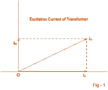
Where;
Iw is the energy supplying component and Iµ is the magnetizing component of the primary no load current Io.
When the secondary coil is open, the back emf produced by the current of the primary coil does not let this current flow to the secondary winding and hence the circuit does not complete and we get no output power.
Behavior of Transformer on loading
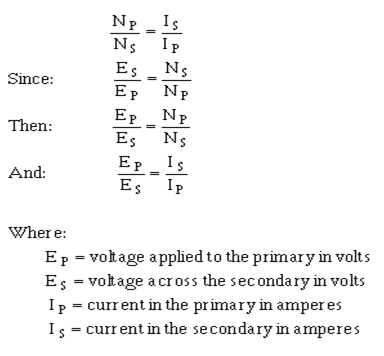
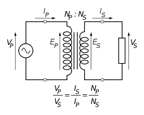
When a load is connected across the secondary windings of the transformer, then the circuit completes, and through Faraday’s law of electromagnetic induction, a current also flows through the secondary coil. This current produces a magnetic field of its own, and depends upon the type of load and the voltage induced in the secondary coil, which in return depends upon the number of turn in the secondary coil, as it is shown through the relation below:
And finally we can write all the above expressions into one equation, which is:
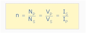
Where;
n is called the Transformation Ratio.
The magneto motive force produced due to this current produces a flux in the secondary coil which opposes the flux of the primary coil, as a result of which a decrease in the net flux is observed. This weakening of the primary flux makes it voltage fall down a bit, and to compensate this flux weakening, an extra current flows through the primary coil and then the net effect is such that it neutralizes the magneto motive force of the secondary coil, so that the total magneto motive force remains changed. This on load representation of the transformer is shown below:
That’s all for today, in the coming post we will check the difference between the Series and Parallel Transformer.
We can join transformers both in series and parallel configuration to increase different parameters. So in the coming we will check what the differences between the two combinations are.
Nasir.