AC power in any electric circuit is the rate of flow of energy at a specific part of that electric circuit. As we all know, the electric energy flow from the generation side toward the consumer load side. But some part of this energy is bounce back to generation side and some part is completely utilized by the load.
Electric power energy that oscillates between source and load is known as reactive power while completely utilized electrical power energy is known as real power. Both the reactive power and real or active or true power are related with the apparent or total power through the following figure.
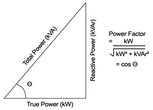
From the figure, it can be deduced that;
(Total Power)² = (True Power)² + (Reactive Power)²
Or (kVA)² = (kW)² + (kVAr)²
The power factor terminology also rises due to interrelation of active and reactive power components. As in active power, both the current and voltage are in phase with each other, hence power factor, which is the phasor angle between voltage and current phasor is zero. Thus power factor (cosine of angle zero) is one, so total power in such a circuit is completely utilized and is only possible for a pure resistive load.
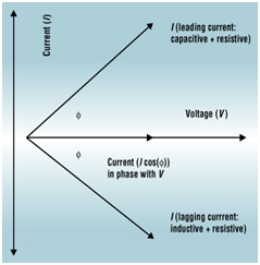
But if the load is not purely resistive (i.e. it is either inductive or capacitive or both inductive and capacitive load along with some resistance), then such load will store part of electric power energy in the form of electric field in capacitor and some part of electric power energy in the form of magnetic field in the inductor. Hence this storage of energy and is swinging back and forth between source and load causes a time lag in the voltage and current phasors, thus rising to a non unity power factor load. Furthermore this power factor is categorized as leading and lagging due to capacitive load and inductive load respectively. It is shown in the following figure.
In usual practice, all the loads are inductive, thus the power factor is always lagging, hence in grid station, a capacitor bank is installed, which is commonly known for the purpose of power factor improvement. This capacitor bank actually store the leading reactive power, and thus when it is made a part of the transmission lines coming in or going out of the grid station, then this capacitor bank transfer the stored leading reactive power, and consequently the phasor angle between voltage phasor and current phasor decreases, thus the active power component is increased and hence power factor is improved.
Furthermore it is common observation that why transformers are rated in kVA and electric motor are rated in kW? It is because that transformer actually transfers the total apparent power from its primary winding to secondary winding while electric motor need some real power consumption for its normal operation, that’s why it is rated in kW.
When a practical transformer is on a no load condition, then still it draw a very small no load current. This no load current is divided into two rectangular components, i.e. active current component and magnetizing current component. The active current component is in phase with the applied voltage, and thus both together contribute for the iron loses and very small primary copper loss. While the magnetizing current component lags the applied voltage by 900 and is responsible for the production of mutual flux in the core. Here again the real power utilization is due to the active current component, because it is only component that is responsible for supplying both iron and copper loses.
This was a basic explanation of Active Power. Did this help you?
i like this information electrical engineering . please tell me calculated to motor running load & inveteor saving percent load mathed .
thanking
regard
riaz bukhari