Hi, here is an article written by a member of the Electrical Engineering community. He has already contributed to the community by writing a first article about the basics and types of electric generators.
Now today’s lecture is about the terminologies related to electric generators. It’s kind of a theoretical knowledge but an electrical engineer should know these terminologies if he wants to work on electric generators.
An electric generator consists of two main parts:
- Stator
- Rotor
The Rotor basically consists of a rotating shaft which is also called the armature of the generator. The armature rotates when the energy is given to it, and produces current.
The stator consists of the stationary field windings, and the magnetic poles. When the armature rotates under the effect of this magnetism, then according to Faraday’s law of Electro Magnetic induction, an emf is induced and hence the current flow.
So we can say that an electric generator works on the principle of Faradays Law of Electro Magnetic Induction. Mathematically, this law can be expressed as:
(e=-N dΦ/dt)
Where dΦ/dt= rate of change of flux.
The Voltage and current produced in the Generator follow the Ohms law as well, according to which the current produced is directly proportional to the voltage, as long as the resistance remains constant.
V=IR
Power produced in the Generator
The product of voltage and current produced is called the power of the generator. P=V * I. This is true if the load is resistive, but in case of Inductive and capacitive loads, some delay occurs in the transmission of this power and hence it is expressed in the form of power Factors.
Power Factors
Power factor is defined as the cosine of the phase angle.
P.F = cos Θ
The total power than becomes:
P= V*I cos Θ
Phase Angle
The phase angle is the angle of lead or lag between the Voltage and the current. In a resistive load, the current and voltage are in line. In a capacitive load, current leads the voltage by an angle of 90 degree and in and inductive load; the voltage leads the current by an angle of 90 degree, so the current lags behind the voltage.
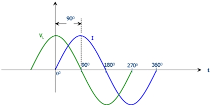
The above figure shows the graph of an inductive load, in which the voltage is leading the current by 90 degree.
Apparent Power
Another term used while describing a generator is its apparent Power. It is the power that is calculated to be absorbed by the system, but in actual, there are losses and other factors which do not help in the calculation of the actual power. That’s why it is called the “Apparent” power. It is expressed in Kilo Volt Amps. When the loads are purely reactive, then the power is also called the reactive power.
Active Power
The Real Power of the circuit can be calculated by taking into account the power factor also, i.e, the current or voltage which is stored by the capacitive or inductive device and the delay in it, is also taken into account. It represents the actual power consumed by the generator or the total amount of work which it is capable of performing. The real power of the generator is also called its active power. It is calculated in Watts.
Efficiency
The efficiency of a device is the ratio of its input power to output power. The losses in power occur due to friction in brushes or bearings, resistance of air and windings and other hysteresis losses.
Awesome blog! Do you have any suggestions for aspiring writers?
I’m hoping to start my own site soon but I’m a little lost on everything.
Would you propose starting with a free platform like WordPress or go for a
paid option? There are so many options out there that
I’m completely overwhelmed .. Any suggestions? Cheers!