This topology was first proposed in 1981. They are also known as neutral point inverters. In 1992 a lot of research work was published on Diode Clamped Multilevel Inverters.
They have their fair share of advantages and disadvantages tied to them but then again, our firm faith in scientists and researchers has kept us calmly waiting for the better version of what we see today.
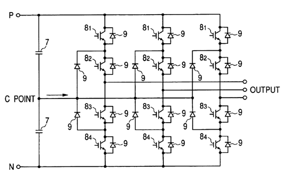
A 3-Level Diode Clamped Multilevel Inverter’s circuitry is shown above. If I try to define the initial target of this inverter, then it would be as simple as converting the DC voltage, which may come through any source even natural resources, into the capacitor voltage.
Moving towards the features of Diode Clamped Multilevel Inverter:
Features
- As the name suggests, and unlike Cascaded H-Bridge Inverters, they need clamping devices.
- Diodes are used as clamping devices.
- Three phase diode clamped multilevel inverters have three legs with a common DC bus.
- This DC voltage is subdivided into switches via capacitors.
- For n-levels, n-1 switch pairs are required.
- One of the switches from each pair should be turned on.
- If one switch is turned on, the other one from the pair should be necessarily off.
- For n-levels, n-1 capacitors are required for clamping DC voltage.
- Switching devices (e.g. transistors) need to block only the supplied DC voltage; however the clamping diodes have a whole different story.
- Each diode has to block the voltage equal to number of switches above it times the supplied DC voltage.
Applications
Keeping in mind the popularity graph of this topology and the number of times it has been proposed by different researchers, I can confidently say that it has many applications. Few of its major uses have been mentioned.
- It can be used with high power motors which have relatively medium speed as a variable drive.
- It can be used very conveniently and efficiently at the interface of high power DC power line and high power AC power line.
- It is also used in static VAR compensation.
Advantages
- High efficiency for switching at fundamental frequency.
- Pre charging of capacitors is done in groups.
- In three phase inverter, all three phases use a common DC bus which reduces the requirement of capacitance.
- Efficient for back to back high power connections.
- Can work with SDCs.
- Low cost.
- Lesser number of components.
Disadvantages
- Quadratic relation between number of diodes and number of levels is difficult to calculate, especially when number of levels get higher it becomes stressful and you would surely want to avoid it.
- Difficulty in real power flow.
- Maintaining certain charging and discharging is difficult.
- Charge balance gets disturbed for more than three levels.
- Limited output voltage.
A lot of research work has been done and is available in detail. For a surface introduction, this article will be sufficient, but our discussion doesn’t end here this way.
A lot more is on its way to keep you people updated. So keep visiting us, multi-level inverters doesn’t end here.
Nasir.
In the first diagram what will be the values and part number use to convert 12vdc to run a three phase 480vac motor