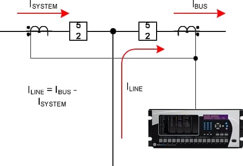
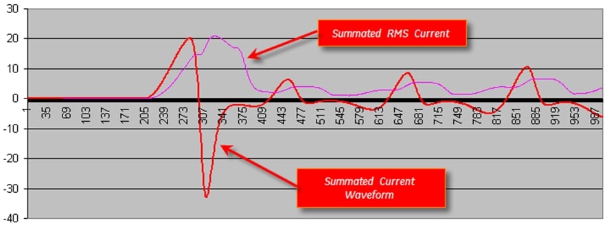
Picture 1. Bus through-fault currents
Current transformers are the interconnection element between the power system and all measurement devices like protective relays. CTs actually lower the value of the primary current to a nominal secondary level in order to be used by meters, protective relays, meters, and monitoring devices.
Here’s a list of the impacts of current Transformers errors on protective relays written by Electrical Engineer Mile.
Current transformers perform in most operating scenarios by reproducing primary current as a secondary current, with little error or distortion. Modern C-class current transformers have error of 1% to 2%, which is high level of accuracy throughout their operating life, which they keep during their operation in the circuit. There are scenarios where transformers do not perform well, and have a negative impact on the protection system and its performance. Current transformers operate differently for each case of current transformer saturation.
Unequal saturation
Current transformers that are identical in turns ratio, accuracy class, and connected load will not perform the same during faults. When two transformers are in parallel, they may saturate differently for the same fault, and can cause undesirable operation of the relays. The sum of the two currents is equal to the current that flows on the line.
In case the transformers are ideal, during a fault on the bus, the sum of the two currents will still be equal to the current that flows on the line. In case the CTs are saturated during this fault, the relay will measure current that is different from the one on the line, like presented on picture 1.
IMG Picture 1. Bus through-fault currents
Current transformer performance during the fault
As seen on the waveforms, the transformers at end of Sub 6 did not perform as it was expected, and the saturation is suspected. The protective relay on the 05-0607A line measured fault current of 1,767A, which is actually the sum of the currents that flow through the current transformers on breakers 501 and 503.
By using a CT saturation analysis tool with a typical current transformer secondary excitation characteristic, a system X/R ratio of 30, maximum flux density in the transformer and a fully offset fault, the current of 1,767A will not cause the transformer to saturate. The fault event was a bus fault on the 05-0607A line, with fault current that flows across the 501 and 503 breakers, as presented on picture 2.
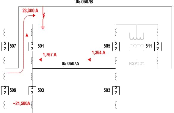
Picture 2. Likely fault currents for event
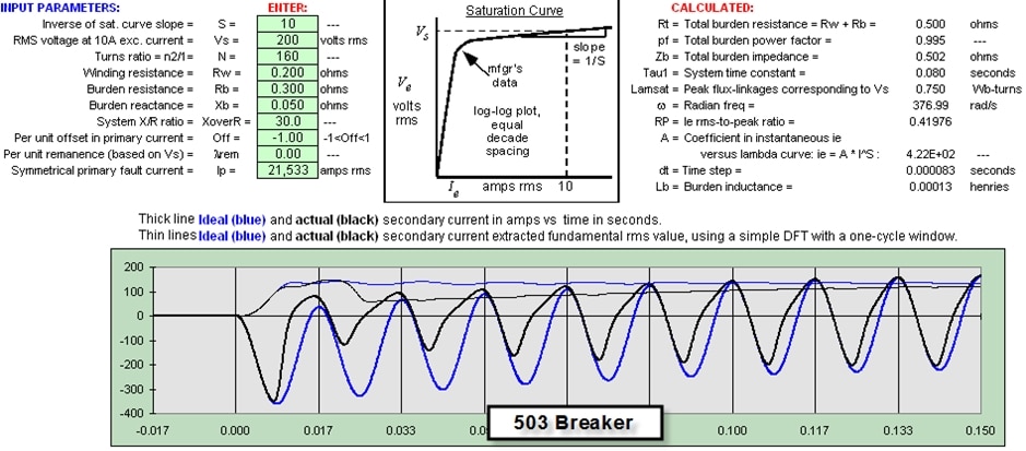
Picture 3. Modeled current transformer performance at 503 breaker
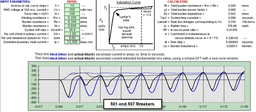
Picture 4. Modeled current transformer performance at 501 and 507
Picture 5. Relay current
On picture 5, you can see the sum of the current from breakers 501 and 503.
Low current saturation
High magnitude fault events are usually the cause of CT saturation. CTs can saturate at low current magnitudes mainly due to the DC component of the fault current, which is usually the reason in circuits with generators nearby, because the generator has a very long DC time constant. The X/R ratio is typically 20-25 in near generators, and rarely goes above 50. Due to the DC component, the terminal and neutral CTs may saturate at different rates, which leads to false differential current.
In this case, the generator is protected by two different microprocessor generator protection relays. The stator differential element for Relay B operated for an external B- Phase to C-Phase fault that is present for 40 cycles. The fault record that was retrieved from Relay B shows that the neutral and terminal CTs measured different currents in both magnitude and phase, with slight difference, which caused the operation of the phase differential element.
On picture 6, we can see the waveforms for the B-Phase current, and the calculated RMS value. The waveforms for the C-Phase are with similar characteristics.
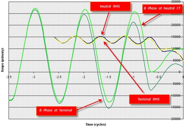
Picture 6. B-phase current waveforms
From the phasor analysis, we can see that we have a 12° error for the B-Phase, and a 13° error for the C-phase. Even these small differences in some cases are enough to cause an incorrect operation of the phase differential element.
From the waveforms and the phasor data, it can be seen that there is unequal CT performance. If we make a mathematical analysis on the date, we can then analyze the performance of the relay B phase differential element.
Conclusion
The design of protective relays, systems, and settings depends of the performance of current transformers. Saturation of transformers is difficult to predict and sometimes leads to undesired operation of the relays
The first example covers the saturation that arises due to high magnitude fault currents. The two CTS that are connected in parallel may saturate differently for the same current faults. The second example describes transformer saturation due to the fault caused by the DC component.
When a current transformer is chosen for an application, the main criteria is the highest possible accuracy class, the highest possible turn’s ratio, and at the end the smallest load possible. There are limits in cost, size, and commitment to specific standards.