Enjoy and feel free to leave comments.
Testing and Commissioning plan
Before commissioning of any electrical setup, certain diagnostic tests are required. Testing And Commissioning plan (T&C) specifies all the criteria for energizing of any sub-transmission overhead line (MV system).
T&C plan should address following parameters:
- a. SLD (Single Line Diagram) of finalized installation.
- b. Tentative schedule.
- c. Relevant SOPs
- d. Tests and procedures with proper summary and final comments by project in charge.
- e. Certifications from relevant authorities.
- f. Complete ‘as installed’ report.
Ground Resistance Test
Grounding test confirms the resistance provided by grounding terminal. It has different standards all over the world. Usually it is supposed to be less than 2 ohm. In more sensitive setups it should not exceed 1 ohm benchmark. Three pole method is considered practical for grounding resistance checks.
Insulation Resistance Test
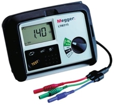
This test is performed with the help of a 10, 12 KV megger, preferably power driven to ascertain the insulation condition of the line. In case 5 kV megger is used, it shall be ensured that the induced voltage is less than the instrument withstanding capacity otherwise it is likely that the instrument may be damaged. In many practical cases, induced voltage exceeds 1000 V and megger test is skipped to avoid equipment damage.

A standard megger used for Insulation Resistance Test
Standard insulation resistance required should be equal to or greater than 1000 Mega Ohms.
IRT is to be carried out First prior to the continuity test to asses and remove any grounding/compromising defects in the transmission line under test.
Hi-Pot Test
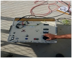
This test is performed by Hi-Pot equipment. Purpose is to verify the leakage parameters. Every phase of the line under test is subjected to 80KV DC supply and leakage measurements are monitored. Exposure duration is usually set to 1 minute. Phoenix-12-7806 equipment is widely used having a range of 100KV.

Phoenix-12-7806 Hi-Pot
If the test equipment trips immediate concern should be equipment failure. After testing and repair (if required) of the equipment, test is usually normal. Leakage current less than 10 mA is desired and all readings should not exceed 5mA if the transmission line is short. DC Voltage of 80 KV is maintained for greater than 60 seconds to rule out any discrepancy.
Phase Verification
This test is performed simply by Ohm meter. Purpose is to confirm that phases marked on both termination points are correct and are verified. R-phase is grounded on one side and ohm meter is connected on R-phase (marked) on the other side. Very low resistance is ideal.
Test is repeated by removing ground on one side and resultantly infinite resistance verifies the phase markings. Same procedure is repeated on remaining two phases.
DC Resistance and Positive Sequence Reactance
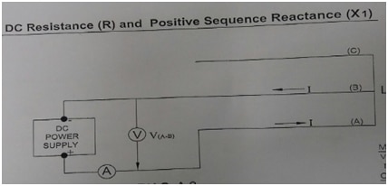
This test is performed to assess DC resistance (R) and positive sequence reactance (X1). These readings are crucial for protection and control settings of grid systems. Theoretical values and practical values should be close and difference should be within acceptable limits.

Circuit scheme for DC resistance and positive sequence reactance
Following steps are taken during the testing/
- a. 3-phase short is placed on all phases as shown in the diagram 3.
- b. Instruments are connected.
- c. DC current is circulated in the line through variable DC supply.
- d. DC amp-meter and volt-meter readings are recorded.
R = V/ (2.IA) Ohm
X1 = √ (Z1)² – R² Ohm
Some values from a real test administered in Pakistan are presented below/
Temperature during testing was 37oC and instrument accuracy class was 0.2. Single phase variable transformer was used.
Zero Sequence Impedance
This test is performed by following the steps mentioned below:
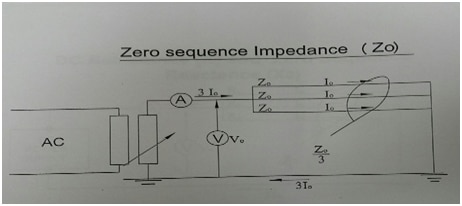
- a. All phases are short circuited at the both ends as shown in the diagram 4.
- b. Instruments are connected on Hub side as shown in the diagram 4
- c. AC current is circulated in the line through variable transformer.
- d. AC amp-meter and volt-meter readings are observed and recorded.
ZO = (3.VO)/ (3.IO) Ohm

Circuit scheme for zero sequence impedance
Some values from a real test administered in Pakistan are presented below:
Temperature during testing was 36.5oC and instrument accuracy class was 1.5.
Zero Sequence Reactance
This test is performed by following sequence wise steps
- a. All phases are short circuited at the both ends and grounded as shown in the diagram attached.
- b. Instruments are connected on one side as shown in the diagram 4.
- c. DC current is circulated through the line through variable DC supply.
- d. Readings are recorded.
Zero sequence test relates impedance offered by the system to the flow of zero sequence current. Impedance is split into positive, negative and zero sequence to simplify the power flow analysis.
Safety Precautions
During all of these tests, following safety measures are vital. Failure to follow these precautions may result in fatal accident (s).
- a. Test should be carried out before connecting the line to systems on both sides.
- b. Area should be barricaded properly.
- c. Personnel present at both ends of the line must stand guard to entry of unauthorized persons and exposure to high voltages being applied.
Further Reading
Please review following literature for better and complete understanding of the subject topic/
Calculation of Transmission Line Parameters From Synchronized Measurements
(https://www.researchgate.net/publication/263528804_Calculation_of_Transmission_Line_Parameters_From_Synchronized_Measurements)
Thanks for reading,
K.
What’s your impressions on that article? Don’t be shy, share your thoughts in our comments section below.

Thank you for sharing good information!