 Mile is one of the community members. He’s a young electrical engineer from Macedonia who likes to share is experience.
Let’s read his essay on grounding systems, based on what he’s experienced in his recent career.
And if you want to share your experience as a young electrical engineer, do not hesitate to contact us.
It is very well known, that in case of short circuit in the power system, the current that appears on the place of the short circuit, is directly transferred to the earth.
The value of the current, which flows through the power lines and in the grounding system itself, and the short circuit time, depend of the type of the grounding of the neutral point of the network and the characteristics of the relay protection system.
In networks with directly grounded neutral point, short circuit currents that flow to the ground, can achieve values of kA. However, the short circuit time in these types of networks is limited to μs.
In power networks with isolated neutral point and in compensated power networks, the short circuit current can achieve value of several amperes, but the time of the short circuit can last for hours. The density of the short circuit current is relatively high, and the voltage potentials on the place of the short circuit receive high values, which can cause serious damage to the system nearby the short circuit place.
These facts are the reason why a grounding system should be implemented. Grounding system is practically the protection, which conducts the short circuit current to the ground at the lowest value of transient resistivity. The grounding system minimizes the hazards that may occur from the voltage potentials that appear on the short circuit place.
Power line grounding system
In this section of the article, the grounding system of 400 kV power line is described. We are going to focus on one mast from the Bitola 2 – Amindeo 400 kV power line.
The mast is grounded to the earth with contour grounding system with the following dimensions of the feet 2,35m x 2,35m, while the distance between the feet is 6m.
Each one of the four feet are placed in form of a square, made of two rings. The upper ring is on depth 0,5m, while the other is on 2m depth. Around the feet is a squared ring with total length of 10,35m and it is placed on 0,7m depth. The contour grounding system is presented on picture 1.
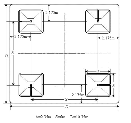
Picture 1 – Contour grounding system
The touch voltage potential difference is 19.29%.
On picture 2 you can see the diagram for the voltage step potential difference in the surrounding area of the mast.
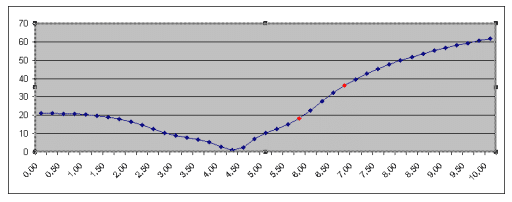
Picture 2 – Voltage step potential difference
At the substation Bitola 2, where the mast is placed, the grounding system is in form of a net, and it is presented on picture 3.
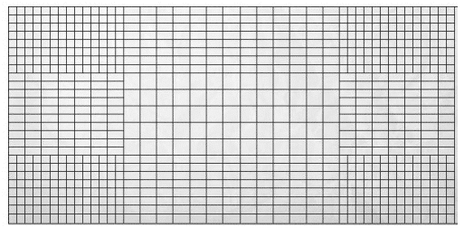
Picture 3 – Grounding system in substation Bitola
The touch voltage potential difference of the grounding system of the substation is 1.47%.
Regulations for grounding systems
Every different state has adopted different regulations and standards regarding the grounding systems. However, one characteristic is the most important when you are making calculations about any grounding system.
That parameter is the allowed value of the touch voltage potential. In table 1 (presented below), there are some comparisons for different countries in the world that have adopted different regulations.
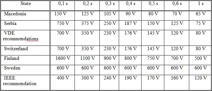
Table 1 – Value of touch voltage
Recommendations for a good grounding system (Conclusion)
As conclusion in this article, we would like to note some of the most important facts engineers should always keep in mind while designing grounding systems.
First, the specific resistivity of the ground in which the systems is placed is one of those factors. Determine the type of soil in which the system should be placed and after that make the calculations.
The second factor is the humidity of the soil. If the soil contains more humidity, that’s a good starting point, because soil with more humidity is a better conductor, and will conduct the short circuit current into ground much faster, than dry soil. Experts recommend pouring salt into ground, because salt is known as material that keeps the humidity in the soil.
The depth is also an important factor. Always place the grounding system as deeper as you can (it is preferred to place the system at least 1m below the surface, on depth in which the ground doesn’t freeze), because if the ground freezes, the conductivity of the system will decrease.
Always stick to these recommendations while designing a grounding system!
Mile.
Thank you Mile for this interesting review. If you have any remarks, don’t hesitate to post a comment below!