Check our loyal member Nasir’s last article from his tutorial on Control Systems.
Introduction
As we discussed earlier there are two ways to analyze the functioning of a control system, time domain and frequency domain analysis. In time-domain analysis the response of a dynamic system to an input is expressed as a function of time. The time response can only be analyzed when the model of system plus nature of input signals are known.
AS the input signals are usually not comprehended completely ahead of time, it is difficult to express the input signals through simple mathematical equations. The behavior of a system that is dynamic in nature is analyzed under typical test signals. These signals are an impulse, a step, a constant velocity and constant acceleration. Another signal is sinusoidal which is of great importance.
There are two components of time response of a system:
- Steady-state response
- Transient response
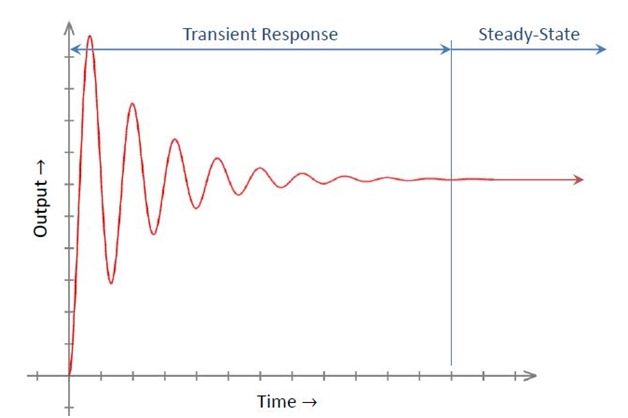
Steady State Response
It is the constituent of the system that only response when the time approaches infinity. It depends upon both the dynamics of the system and the input quantity. It is analyzed by using different test signals like step, ramp or parabolic. Then it is examined using final value theorem.
Transient Response
The constituent of any control system that disappears with time is called transient response of a system. It depends upon the poles of the system and not on input or its type. So the transient response can be analyzed easily using step input.
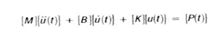
The general equation is given by:
![]()
Transient response analysis computes the behavior of structure given to time-varying excitation. There are two different numerical methods used to analyze transient response:
- Direct Transient Response
- Modal Transient Response
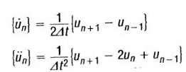
Direct Transient Response
In direct transient response we perform integration on coupled equations of motion to find the structural response.
By using central finite difference representation for the velocity and acceleration at discrete times:
Now,
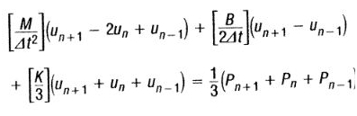
The equation of motion can now be written as:
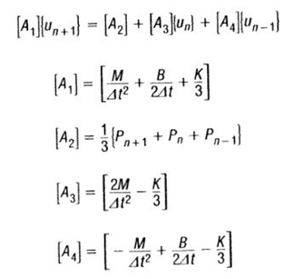
Where,
Matrix [A1] is dynamic matrix while [A2] [A1] is the force applied. The transient response is calculated by modifying the applied force matrix [A2] with the terms [A3] and [A4]
Straightforwardly [M], [B] and [K] are supposed to be constant during the whole time of analysis and assumed to be not changing with time. What benefit this equation provides that if
![]() t remains constant throughout the analysis then Matrix [A1] need to be decomposed one time only but if
t remains constant throughout the analysis then Matrix [A1] need to be decomposed one time only but if ![]() t is changed then Matrix [A1] must be re-decomposed which can be very difficult process in huge operations.
t is changed then Matrix [A1] must be re-decomposed which can be very difficult process in huge operations.
One other benefit of direct transient response analysis is that time interval of output may be larger than the time interval of solution.
Damping In Direct Transient Response
Matrix [B] is used as damping matrix; it shows the dissipation of energy which is the characteristic of structure. The damping matrix consist of quite a few matrices:
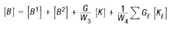
Where, G shows overall structural damping coefficient, [B1] shows damping elements and B2GG, [B2] is B2PP direct input matrix and transfer function, [K] is global stiffness, [KE] is element stiffness, [GE] is element structural damping coefficient, [W3]/[W4] is frequency of interest in radians per unit time.
Modal Transient Response
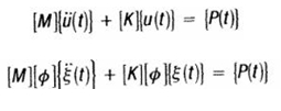
Modal transient response is another way to compute the system’s transient response. In this technique, we use two shapes of structure to trim down the size of the equations and then uncouple them (when no damping or modal is used). By this way our numerical integration is more accurate.
![]()
If we ignore damping, the equation becomes:
Now,
![]()
Where, ![]() [M]
[M] ![]() is modal overall mass matrix,
is modal overall mass matrix, ![]() [K]
[K] ![]() is modal overall stiffness matrix,
is modal overall stiffness matrix, ![]() {P} is modal force vector.
{P} is modal force vector.
The uncoupled form is written as:
![]()
The above written equation shows the modal equations are uncoupled. Where mi is i-th mass, ki is i-th stiffness, pi i-th force.
Damping In Modal Transient Response Analysis
The damping matrix [B] is given by equation:
![]()
When matrix [B] is there than modal transient is solved in terms of coordinates and direct transient integration is used. Equations are comparable with direct transient equations but these are in coordinates form.

Conclusion
There are two components of any time domain analysis. In this tutorial we have discussed one of them that is transient response of a system in detail. We studied direct transient response and modal transient response and damping in both of them.
In the upcoming tutorial we will introduce you to Laplace transform which is one of the most important part of this tutorial. So don’t miss it out.
Nasir.