Ismael is specialized in designing electrical systems (LV and MV) for commercial, industrial, and residential. Let his 5 years of experience enlighten you and read now the answer to how to specify medium voltage switchgear for industrial plant!
IP codes
As Medium Voltage Switchgear often entirely enclosed within the building, it is paramount to specify the specification for its enclosure. IP code (Index of Protection or International Protection or Ingress Protection) state the environmental protection against the ingress of solid foreign objects and water.
The IP code is based on IEC 60529 Degrees of Protection Provided by Enclosures and consist of two numbers. The numbers reflect the protection requirement. The higher the number, the more stringent the protection requirement. The meaning of two numbers IP code are:
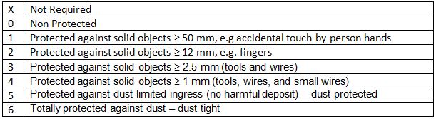
- Protection from solid objects or materials
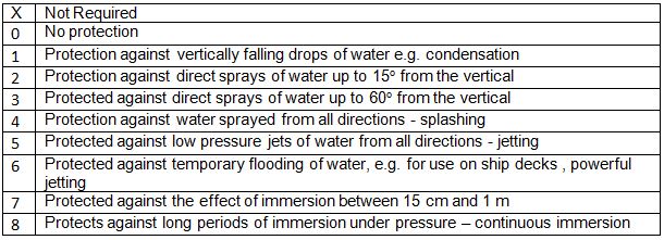
- Protection from liquids (water)
IP First number – Protection against solid objects
IP Second number – Protection against liquids
Voltage Rating
Operating Voltage
Operating Voltage is the voltage across the switchgear terminal.
Rated voltage (kV)
Rated voltage is the maximum voltage value which can be received to the switchgear/circuit breaker in kV rms. The rated voltage is higher than operating voltage.
For IEC standard, the voltage rating are (in kV)
3.6 – 7.2 – 12 – 17.5 – 24 – 36
Insulation Level Rating
Lightning Impulse withstand Voltage
The ability of the switchgear to withstand overvoltage caused by lightning
Power Frequency withstand Voltage
The ability of the switchgear to withstand overvoltage caused by opening or closing of a circuit.
Voltage rating of the medium voltage switchgear is shown in the table below:
| Rated Voltage | Rated Lightning Impulse withstand voltage 1.2/50 μs 50 Hz kV peak | Rated Power Frequency Withstand Voltage 1 min kV r ms | Normal Operating Voltage kV rms |
| 7.2 | 60 | 20 | 3.3 to 6.6 |
| 12 | 75 | 28 | 10 to 11 |
| 17.5 | 95 | 38 | 13.8 to 15 |
| 24 | 125 | 50 | 20 to 22 |
| 36 | 170 | 70 | 25.8 to 36 |
Current Rating
The rated current that can flow through the bus bar when the switchgear is in close position. IEC sets the maximum permissible temperature value not exceeding 400 C.
Frequency Rating
Two frequencies are used in the world, 50 Hz or 60 Hz
Fault Level / Short Circuit Rating
Safety is the most important criteria in selecting proper switchgear. Hence, switchgear must be able to:
a) Withstand and operate the continuous operating current and overload.
b) Interrupt the short circuit current;
c) Withstand a short-circuit switching.
d) Interrupt the no load currents without an excessive overvoltage (downstream open).
Short circuit ratings which used in IEC standard are 25 KA, 31.5 kA, and 40 kA.
Short circuit rating usually stated in 2 different capacity in times, 1 seconds and 3 seconds. The duration is associated with thermal withstand. The longer the duration, the longer the switchgear will able to withstand the short circuit.
Ex: 40 kA for 3 seconds. It means the switchgear is able to withstand 40 kA short circuit for 3 seconds.
Breaker rating
Operating voltage
Operating voltage is the maximum voltage value which can be received to the switchgear. For instance, if a switchgear has 24 kV operating voltage, it can be installed for up to 24 kV system.
Momentary current
Momentary current is the maximum capability a CLOSED switch of the breaker to withstand rms asymmetrical current (usually for 10 cycles) including the dc component [2]. For example, Transformer Inrush Current.
Maximum interrupting Ampere
Maximum interrupting Ampere is the highest rms current that can be interrupted by the breaker in any value of the voltage. For instance, a load interrupting switch which has 600 A interrupting rating means it will switch 600 A of current.
Interrupting MVA
Interrupting MVA is the products of the voltage multiply by the rated short circuit current.
MVASC = √3 VLL x IL
Where,
VLL = Line to line voltage
IL = Interrupting current in kA
Internal Arc Classification (IAC) for safety requirement
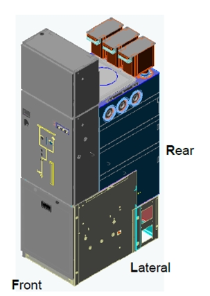
Figure 1. Internal Arc Classification | image from [3]
Internal Arc Classification is based on IEC 62271-200 and is intended to verify the effectiveness of the design in protecting persons in case of an internal arc. The classification of internal arc is described as follow:
- IAC: Internal Arc Classification
- Accessibility type A,B, or C:
A – Restricted to authorised personnel only. Distance of indicator 300mm from panel.
B – Unrestricted accessibility including general public. Distance of indicator 100mm from panel.
C – Restricted by installation out of reach. The minimum admissible height of installation shall be stated by the manufacturer. - FLR: Access from the f(F-Front), from the lateral/sides (L-lateral), and from the rear (R-Rear)
- I: Test current
- t: Arc duration
Example : IAC AFL 24kA x 1s
References
[1] “The Engineering Toolbox,” [Online]. Available: http://www.engineeringtoolbox.com/ip-ingress-protection-d_452.html. [Accessed 13 January 2016].
[2] “Schneider Electric,” Schneider, [Online]. Available: http://www.schneider-electric.us/sites/us/en/support/faq/. [Accessed 12 January 2016].
[3] Development of standards for MV Switchgear for Arc Flash protection, 2013.
[4] Schneider, Medium Voltge Technical Guide, Scheneider Electric Industries SAS, 2009.
Thank you everybody for reading,
Ismael.
Any impressions? Leave a comment below.