Home › Electrical Engineering Forum › General Discussion › Parallel transformer electrical distribution › Re: Parallel transformer electrical distribution
Francois said:
Redondancy of supply is often a must ; protection coordination is not easy to master : case of parallel MV/LV transformers.
This case is typical for hospital and even office building where service continuity constraint is high.In fact, parallel MV/LV transformers are used for two reasons:
- redundancy is mandatory for installation continuity of supply,
- constraints on physical size of the transformers.
To ensure the maximal level of continuity of supply a particular attention shall be attach to LV protection coordination at the transformer level.
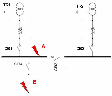
Case of a short circuit in A
The expected protection operation is the following:
* CB3 and CB1 should operate to eliminate the short circuit current and CB2 should still closed.
This requires some specific constraints on CB1, CB2 and CB3 settings:
* these 3 protections shall operate with the same current setting,
* the solution consists in using chronometric cascading between CB3 and CB1/CB2.The proposed solution consists in setting CB1 and CB2 short delay to an upper value than CB3 short delay.
In that case for the short circuit in A the operating sequence is:
* CB3 opening,
* CB1 opening.[caption id="attachment_824" align="aligncenter" width="453" caption="Electrical distribution network"]
[/caption]
Case of short circuit in B
The expected protection operation is the following:
* only CB4 should operate.The problem is that in some case the rating of CB4 may be greater or close to the rating of CB1 and CB2. Despite breaker selectivity table given by circuit breaker manufacturers gives no solution, breaker selectivity may be possible thanks to the fact that CB1 and CB2 see half of the short circuit current compared to CB4.
This is my proposal of designing a good protection coordination in this case of parallel MV/LV transformersChristian Collombet
Dear Mr. Francois ;
First, the schematic diagram shows ” CB1, CB2 ” for 2 tranformers and ” CB3 ” as a coupler, that means we have to possibitilies taht are :
– Each transformer supply his load and the coulper ” CB3 ” will close once we have a problem in one of 2 transformers, in this case, we should install between these 3 CB's a special Mechanical Interlocking.
– If the 2 transformers work in parallel, in the fault's case in point ” A “, the methode that you mention using a ” Timing delay ” is OK, but please it's a ” Chronometric Discrimination or Chronometric Selectivity study ” and not Cascading. Because as we know we using the Cascading advantge to optimize the breaking capacity value for outgoing CB's by using the limitaion of short circuit current advantage of the main CB.
Regards.