Home › Electrical Engineering Forum › General Discussion › Parallel transformer electrical distribution
- This topic has 14 replies, 4 voices, and was last updated 11 years, 9 months ago by
 Anonymous.
- AuthorPosts
- 2010/10/13 at 9:56 am #10243
 FrancoisParticipant
 Redondancy of supply is often a must ; protection coordination is not easy to master : case of parallel MV/LV transformers.
This case is typical for hospital and even office building where service continuity constraint is high.In fact, parallel MV/LV transformers are used for two reasons:- redundancy is mandatory for installation continuity of supply,
- constraints on physical size of the transformers.
To ensure the maximal level of continuity of supply a particular attention shall be attach to LV protection coordination at the transformer level.
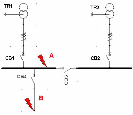
Case of a short circuit in A
The expected protection operation is the following:
* CB3 and CB1 should operate to eliminate the short circuit current and CB2 should still closed.
This requires some specific constraints on CB1, CB2 and CB3 settings:
* these 3 protections shall operate with the same current setting,
* the solution consists in using chronometric cascading between CB3 and CB1/CB2.The proposed solution consists in setting CB1 and CB2 short delay to an upper value than CB3 short delay.
In that case for the short circuit in A the operating sequence is:
* CB3 opening,
* CB1 opening.[caption id="attachment_824" align="aligncenter" width="453" caption="Electrical distribution network"]
 [/caption]
Case of short circuit in B
The expected protection operation is the following:
* only CB4 should operate.The problem is that in some case the rating of CB4 may be greater or close to the rating of CB1 and CB2. Despite breaker selectivity table given by circuit breaker manufacturers gives no solution, breaker selectivity may be possible thanks to the fact that CB1 and CB2 see half of the short circuit current compared to CB4.
This is my proposal of designing a good protection coordination in this case of parallel MV/LV transformersChristian Collombet
2010/10/13 at 9:59 am #11533AnonymousGuestThis is a system with two different Electric supply circuit with common load which is in CB4, in this case, one is the Normal source of power and the other in emergency power like Standby Generator.
If both are supplying the load in parallel operation, the system must be properly synchronize.
If CB3 is the tie breaker, and will operate only when CB! has no loss power, then CB3 must be designed with mechanical and electrical interlocking system to avoid motorization of the smaller power supply and for safety purposes.
2010/10/13 at 9:59 am #11534AnonymousGuestThank-you for your comments.
This is of course the case parallel transformers fed by a common MV power supply.
The purpose is here to define a way to set a reliable discrimination between CB1, CB2 and CB3 in case of fault in A in ordre to keep TR2 and its dowstream feeder under voltage.2010/10/13 at 9:59 am #11535AnonymousGuestI see. Thanks.
They have a common power supply and not different. I can suggest then that certain faults can be avoided by improving power quality. PLUS IT CAN SAVE ENRGEY. Try the ECTROFLOW SYSTEM.
the power quality solutions can balance the three phase load automatically, it can stabilize voltage, increase power factor up to 100%, mitigate Harmonics to non destructive level, can supply the loss phase in case of single phasing fault, it has 10 features.2010/10/13 at 9:59 am #11536AnonymousGuestHello !
Wonderfull blog for electrical engineer and for electricians !
I have a question : Where I can get gratis download soft for Electrical Cad 2004 ?
Thanks!2010/10/13 at 9:59 am #11538AnonymousGuestcoming back to your request can you be a little bit accurate, what are you looking for exactly ?
2010/10/13 at 9:59 am #11539AnonymousGuestThe above application for two different load from two different sources through 2 CBs( CB1+CB2 ) and another CBs that is called CB Coupler ( CB3 ) .
Each Tr. can feed the two loads through ( CB3 ) in case one of the transformer or its CB was failled . This application is call 2 out of 32010/10/13 at 9:59 am #11540AnonymousGuesttwo transformers are coupled ,then why they are showing different loads
2010/11/01 at 4:12 pm #11592adminKeymasterDorin Pestereanu said:
Hello !
Wonderfull blog for electrical engineer and for electricians !
I have a question : Where I can get gratis download soft for Electrical Cad 2004 ?
Thanks!I think in the operation of transformer is severly depend upon the loading of trasformer in distribution system as in msximium loading efficiency of distribution trasformer decreses which is a big reason for distribution loss parallel operation of trasformer is good solution for that.
2011/06/15 at 1:19 am #12192AnonymousGuestThere is a company that supply transformers and parts from China, they can answer a lot of highly technical questions like iron core specification, copper wire resistance and specific calculations, insulation ratings (electrical and thermal) and few other thinks:
http://pa-international.com.au/index.php?option=com_content&view=article&id=122
Come in handy if you have any specific questions and trying to work out parameters of a new transformer been designed.2011/06/16 at 12:26 pm #12195Spir Georges GHALIParticipantFrancois said:
Redondancy of supply is often a must ; protection coordination is not easy to master : case of parallel MV/LV transformers.
This case is typical for hospital and even office building where service continuity constraint is high.In fact, parallel MV/LV transformers are used for two reasons:- redundancy is mandatory for installation continuity of supply,
- constraints on physical size of the transformers.
To ensure the maximal level of continuity of supply a particular attention shall be attach to LV protection coordination at the transformer level.
Case of a short circuit in A
The expected protection operation is the following:
* CB3 and CB1 should operate to eliminate the short circuit current and CB2 should still closed.
This requires some specific constraints on CB1, CB2 and CB3 settings:
* these 3 protections shall operate with the same current setting,
* the solution consists in using chronometric cascading between CB3 and CB1/CB2.The proposed solution consists in setting CB1 and CB2 short delay to an upper value than CB3 short delay.
In that case for the short circuit in A the operating sequence is:
* CB3 opening,
* CB1 opening.[caption id="attachment_824" align="aligncenter" width="453" caption="Electrical distribution network"]
[/caption]Case of short circuit in B
The expected protection operation is the following:
* only CB4 should operate.The problem is that in some case the rating of CB4 may be greater or close to the rating of CB1 and CB2. Despite breaker selectivity table given by circuit breaker manufacturers gives no solution, breaker selectivity may be possible thanks to the fact that CB1 and CB2 see half of the short circuit current compared to CB4.
This is my proposal of designing a good protection coordination in this case of parallel MV/LV transformersChristian Collombet
Dear Mr. Francois ;
First, the schematic diagram shows ” CB1, CB2 ” for 2 tranformers and ” CB3 ” as a coupler, that means we have to possibitilies taht are :
– Each transformer supply his load and the coulper ” CB3 ” will close once we have a problem in one of 2 transformers, in this case, we should install between these 3 CB's a special Mechanical Interlocking.
– If the 2 transformers work in parallel, in the fault's case in point ” A “, the methode that you mention using a ” Timing delay ” is OK, but please it's a ” Chronometric Discrimination or Chronometric Selectivity study ” and not Cascading. Because as we know we using the Cascading advantge to optimize the breaking capacity value for outgoing CB's by using the limitaion of short circuit current advantage of the main CB.
Regards.
2011/06/18 at 10:14 am #12198Spir Georges GHALIParticipantSpir Georges GHALI said:
Francois said:
Redondancy of supply is often a must ; protection coordination is not easy to master : case of parallel MV/LV transformers.
This case is typical for hospital and even office building where service continuity constraint is high.In fact, parallel MV/LV transformers are used for two reasons:- redundancy is mandatory for installation continuity of supply,
- constraints on physical size of the transformers.
To ensure the maximal level of continuity of supply a particular attention shall be attach to LV protection coordination at the transformer level.
Case of a short circuit in A
The expected protection operation is the following:
* CB3 and CB1 should operate to eliminate the short circuit current and CB2 should still closed.
This requires some specific constraints on CB1, CB2 and CB3 settings:
* these 3 protections shall operate with the same current setting,
* the solution consists in using chronometric cascading between CB3 and CB1/CB2.The proposed solution consists in setting CB1 and CB2 short delay to an upper value than CB3 short delay.
In that case for the short circuit in A the operating sequence is:
* CB3 opening,
* CB1 opening.[caption id="attachment_824" align="aligncenter" width="453" caption="Electrical distribution network"]
[/caption]Case of short circuit in B
The expected protection operation is the following:
* only CB4 should operate.The problem is that in some case the rating of CB4 may be greater or close to the rating of CB1 and CB2. Despite breaker selectivity table given by circuit breaker manufacturers gives no solution, breaker selectivity may be possible thanks to the fact that CB1 and CB2 see half of the short circuit current compared to CB4.
This is my proposal of designing a good protection coordination in this case of parallel MV/LV transformersChristian Collombet
Dear Mr. Francois ;
First, the schematic diagram shows ” CB1, CB2 ” for 2 tranformers and ” CB3 ” as a coupler, that means we have to possibitilies taht are :
– Each transformer supply his load and the coulper ” CB3 ” will close once we have a problem in one of 2 transformers, in this case, we should install between these 3 CB's a special Mechanical Interlocking.
– If the 2 transformers work in parallel, in the fault's case in point ” A “, the methode that you mention using a ” Timing delay ” is OK, but please it's a ” Chronometric Discrimination or Chronometric Selectivity study ” and not Cascading. Because as we know we using the Cascading advantge to optimize the breaking capacity value for outgoing CB's by using the limitaion of short circuit current advantage of the main CB.
Regards.
Dear Mr. François ;
Excuse-me last time, I haven't a time to explain my opinion for ” CB4 “.
For all outgoings like ” CB4 ” with 2 transformers I done and do the following :
As the specifications for ” CB4 ” should be defined in the worth case, I define the main specifications of CB… as follow :
– The ” Breaking Capacity ” of ” CB4 ” will be definded after calculation the maximum short circuit current ” Isc3max ” taking into concideration that the 2 transformers are working in parallel.
– The ” Magnetic Protection Setting ” will be definded after calculation the minimum short circuit current ” Isc1min ” and the earth fault ” If ” ( if we don't using Earth Fault Protection ) takning into concideration that only one transformer is working.
– The value of ” Making Short Circuit Current ” should be defined accordingly to the calculated value of ” Isc3max “.
– The other specification can be defined normally.
Noting that in this case :
– The ” Timing delay ” for magnetic Protection should be absolutly useed for ” CB1, CB2, CB3 “.
– We should be attention of the setting of ” Instantaneous Protection ” in ” CB1, CB2, CB3 ” if existed.
Regards.
2011/06/20 at 2:43 pm #12206AnonymousGuestparallel MV/LV transformers are a must
2012/03/08 at 4:36 am #12872AnonymousGuestI think I just lost it. You guys are awesome! I am still studying all this, but hopefully one day I will be able to speak with you the same “language”.
2014/09/23 at 1:02 am #13590AnonymousGuestIt’s going to be ending of mine day, however before end
I am reading this impressive piece of writing
to increase my know-how. - AuthorPosts


- You must be logged in to reply to this topic.