Home › Electrical Engineering Forum › General Discussion › What is smart meter on middle voltage? (back to basics)
- This topic has 1 reply, 2 voices, and was last updated 10 years, 3 months ago by
Anonymous.
-
AuthorPosts
-
2014/11/05 at 4:23 pm #11207
Steven Mill
ParticipantHi, this is Steven Mill. It’s been a long time so I’m coming back with a back to basics article. Hope you’ll enjoy.
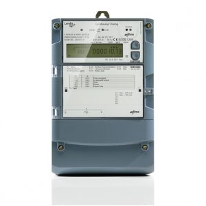
The electricity smart meter is a device that measures electricity in the same way as the ordinary electricity meter but with the difference that it measures and stores much more data and parameters than the ordinary electricity meter.
Below you can see how one electricity smart meter for middle voltage looks like.
- The smart meter measures and store consumed electricity (active and reactive) per hour or less and thus gives very accurate load profile
- It measures instantaneous currents and voltages and store them every hour or less
- It also measures the power factor (cosϕ)
- Measures instantaneous powers and reached powers over a given period
- Register the voltage dropout
The smart meter can measure other parameters depending of the power supplier needs.
These smart meters are to be mounted on large electricity consumers e.g. factories, manufacturing workshops, office buildings etc.
After the data is stored the smart meter sends it to the power supplier. For smaller areas you can build LAN network and for larger areas you can use the mobile operator’s network.
How the electricity on middle voltage is measured?
As it is well known the formula for electricity measurement is: P=U*I*cosϕ, where:
- P is electricity power
- U is voltage
- I is current
- cosϕ is power factor
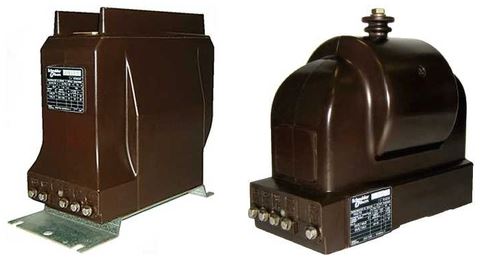
The electricity on middle voltage is measured by voltage and current transformers.
- The voltage transformers are converting the voltage from 6, 10, 20, 35kV to 58/100V
- The current transformers are converting the current flow on the grid, proportionally and without phase displacement in current with smaller value (5A or 1A)
[caption id="attachment_8567" align="aligncenter" width="481"]
Current measurement transformer / Voltage measurement transformer[/caption]
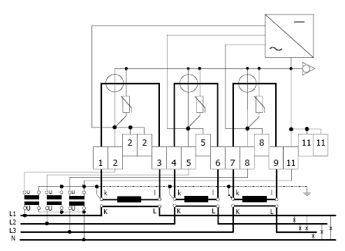
Below is the connection diagram:
This is a connection diagram with 3 voltage and 3 current transformers. The designations are as follows: from 1 to 11 are clamps of the meter.
1 Beginning of the first secondary current 2 First voltage 3 End of the first secondary current 4 Beginning of the second secondary current 5 Second voltage 6 End of the second secondary current 7 Beginning of the third secondary current 8 Third voltage 9 End of the third secondary voltage 11 N – phase neutral U Primary side of the voltage transformer u Secondary side of the voltage transformer K Beginning of the primary side of the current transformer k Beginning of the secondary side of the current transformer L End of the primary side of the current transformer l End of the secondary side of the current transformer L1 First phase L2 Second phase L3 Third phase N Neutral There is a diagram with 2 current and 2 voltage transformers but it is not very common.
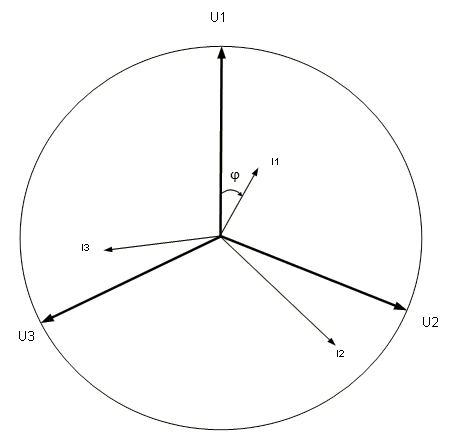
On the picture below you can see a vector diagram which the meter can draw during the measuring.
Conclusion
In conclusion we can say that the smart meters on middle voltage can be very useful ; not only for the measured electricity but because of the fact that they can measure many different parameters which the power supply company can analyze and improve the quality of their services.
It is also possible that the meter’s vector diagram can be seen at any time from a distance which is very useful because if there is any fault in the measurement group it would be reflected there.
Steven Mill.
What’s your opinion on this article?
2014/11/30 at 3:00 am #13618Anonymous
GuestBack to basics….yes its really a good and simple way of explaining the purpose and funchion of the smart metering.
-
AuthorPosts
- You must be logged in to reply to this topic.

 Current measurement transformer / Voltage measurement transformer[/caption]
