Home › Electrical Engineering Forum › General Discussion › Variable Speed Drivers
- This topic has 1 reply, 2 voices, and was last updated 8 years, 11 months ago by
Anonymous.
-
AuthorPosts
-
2013/09/10 at 8:27 am #11079
admin
KeymasterIntroduction
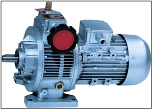
Variable speed drivers are also known as adjustable speed drivers. As clear by the name their use involves the regulation of machinery speed.
Various industrial procedures and processes including assembly lines result in production of various products which also require various speeds for operation.
When the need of the product is the regulation of flow movement starting from the pump or fan the best way is to vary the speed as it will end up with saving the energy also.
If the drive provides option to vary the speed by selecting a pre-set range then it is said to be adjustable speed and if the speed can be varied without the need to utilize pre-set ranges then it is called variable speed.
Adjustable and variable speed drivers may be mechanical, hydraulic, electromechanical or even electronic.
Why use adjustable speed drivers?
The main purpose behind building an adjustable speed driver was only process control at first. Later with the demand of the users, energy conservation was also added as a function.
These two characteristics later became the main reason behind the vast usage of these speed drivers.
Adjustable speed drivers: Process control
When process control is the function of the drivers than they provide the user with:
- A better and smooth functionality.
- Means to control the acceleration.
- The speed can be adjusted differently for each different process.
- Process variables can be changed and adjusted.
- If the process is yet to be made ready then the driver can be set for slow operation to buy time.
- The rate at which the product is produced can be adjusted.
- The positioning is also done accurately.
- The torque or tension produced during the functioning can also be controlled.
- Adjustable speed drivers help in catching the spinning load once the outage is done.
To understand the concept of adjustable speed drivers more an example would be the best way to explain it. The course of movement of the sewage present in the sewage lift station is from sewer pipes to a wet well location through gravity.
A treatment plant is present next to where all the sewage is further pumped. In this case if the pumps used are seed pumps then as per their function they will start working when the water level reaches a certain high limit and stop when it drops below that level.
Because of this the pump gets on and off frequently. This affects the motor when it starts by producing heavy flow of electric current and so the motor and the power control equipment go into an electromagnetic and thermal stress.
Mechanical and hydraulic stress is also produced in the pumps and the pipes. As a result of all the stresses the choice left for the sewage treatment plant is to now use the process and adjust the surges being produced in the sewage flow.
If the speed pumps are now replaced with the adjustable speed drivers what happens is that the sewage continues to flow at an average speed with the speed varying as the sewage level varies.
The outflow and inflow average is balanced and the whole operation runs without any difficulty.
Division of adjustable speed drivers into various categories
The mechanical power transmission to machinery and the application of speed adjustment method in them date back to when powered machinery usage started.
The water wheels and steam engines were previously used to produce mechanical power which was controlled using the mechanical speed changers which were later replaced by the electric motors.
In the industrial drive markets presently there is tough competition between the mechanical, hydraulic and electric drivers.
The adjustable speed drivers are further divided on the basis of the control type and the drivers. The control can be achieved through two ways. One, a potentiometer or linear hall effect device could be used. Both these are dust and grease resistant. The other is to use a rotational detector including the Gray code optical encoder for automatic control.
Drive types
The drive is the controller part of the machine without the motor. It is divided into three types, DC motor, eddy current and AC motor drives.
- DC Drives: These drives utilize DC motors for the speed control process. DC motor has a direct relation with the armature voltage and inverse relation with motor flux which in turn is a function of the field current. So either tech can be used for speed control.
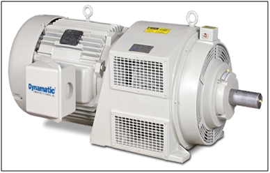
- Eddy Current Drives: a fixed speed motor and an eddy current clutch are the two main components of these drives. A small air gap is used as a separation between the fixed and adjustable speed rotors present in the clutch.
In the field coil through the use of direct current, magnetic field is produced which is the deciding factor of the amount of torque essential to be transmitted between the input and the output rotor.The speed of the closed loop is controlled by altering the current through the clutch and only that required torque to properly work with at a specific speed is provided.
- AC Drives- These drives are based on the working of AC speed control systems. In these drives slip-controlled wound rotor induction motor (WRIM) drives are used.
The motor slip is altered through the rotor slips to control the speed. The alteration could be done in two ways.The first method is to recover the slip power fed back to the stator bus using electronic means. The second is by changing the resistance in the rotor circuit present because of the external resistors present in it.
Both eddy current drivers and WRIM based drivers have long been out of the game because they are less efficient when compared with the WRIM drives based on AC-DC-AC technology.
2016/03/25 at 4:07 am #13769Anonymous
GuestDear all:
I have Motor RPM 885 and Pump RPM 350 for Diesel cargo pump I want fix the motor to pump but have deferent in RPM I want variable Speed Control Driver fix with motor to adjust the RPM the detail the motor is.
RPM – 885
V – 240
A – 134
KW – 75
HP – 100Best Regard
Eng: ODAY M.
00971556937010 -
AuthorPosts
- You must be logged in to reply to this topic.

