Home › Electrical Engineering Forum › General Discussion › Using Capacitors in Electrical Circuits
- This topic has 3 replies, 4 voices, and was last updated 12 years, 9 months ago by
 PeterKnauf.
- AuthorPosts
- 2013/07/29 at 8:51 am #11057
 Steven MillParticipant
Introduction
Use of Shunt capacitors in a High Tension (HT) or Low Tension (LT) installation has become a necessity and also mandated by most of the utilities worldwide. Let us understand some concepts behind the use of a Shunt Capacitor.
Need for Capacitor Installation
There is a growing need for energy conservation and all efforts are being made towards the same. On the other hand, the electrical loads in almost all categories of customers i.e. Industrial, Commercial, Residential, Agricultural are inductive loads in nature.
These inductive loads include: electrical equipments and devices like: Induction Motors, Fans, Industrial A.C. machines. With the advent of technology and greater level of automation in the last few decades, the electrical load mix is greatly becoming Inductive in nature.
The drawback of these inductive machines is that they draw a huge amount of Reactive Power (KVAr) from supply side, thus causing lowering of Power Factor (P.F.).
- Power Factor:
Power Factor is defined as ratio of Real Power (expressed in Watts) to Apparent Power (measured in Volt-Ampere VA). The Real Power is what is actually delivered and consumed by the electrical device. Thus, lower the value of Real Power, lower will be the Power Factor.
An ideal case Power factor has to be 1.0 however, it is practically impossible to equate Real Power to Apparent Power therefore, at practical levels the equipments operate at a Power Factor of 0.9 to 0.95.
A fall out of this low Power Factor is that it puts a burden on the electrical supply side, as this forces the utility to generate more power (KVA) than its required size.
By installing a Shunt Capacitor, it ensures that the reactive Power (KVAr) in the system is compensated locally with its own KVAr rating. Thus, it prevents the varying reactive power demands hitting the supply side and eventually protects the supply side equipments (transformers, generators etc.)
It is a common practice by utility companies to charge penalties to consumers who fall below the set benchmark value of Power Factor. For large Industrial consumers this may mean a huge financial impact. Hence, electrical managers and designers always keep a special eye on operating conditions of Power Factor and try to compensate it with appropriate sized Capacitors installed.
Installation of a Shunt Capacitor
Shunt Capacitors are installed closer to the inductive load side.
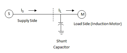
The capacitors may energized continuously or switched on and off during load cycles.Figure below shows a circuit with Shunt capacitor applied at load side:

As seen in figure above, the shunt capacitor is connected nearer to inductive load (Induction motor in this case). Depending on the type of capacitor chosen, it may be fixed or switched operation capacitor and provides Reactive power compensation (VAR) at the load side, thus preventing the Supply side from getting affected.
Benefits of Reactive Power Compensation using Shunt Capacitor
- Increased System Capacity – As the installed Shunt Capacitor improves the power factor and reduces circuit current for given load, therefore a greater KVA can be carried to the load before enhancing the supply side.
- Improved Voltage conditions – Since Reactive power is better managed, it does not cause voltage fluctuations at feeder level, and thus, there is a good balanced load condition prevailing in the circuit
- Reduction in Power System Losses – Use of shunt capacitor improves Power Factor and reduces the currents, it also causes the associated I2R losses to go down. Thus there is a reduction in Power system losses.
- Reduced Energy Bill and Avoiding Penalties – A higher power factor keeps the monthly energy bill down and thus helps possible penalties by the utility company due to crossing of set Power factor limits.
Do you agree with my vision of the use of capacitors in electrical circuits? Let’s talk about it and thanks for reading.
2013/07/31 at 12:11 pm #13342Spir Georges GHALIParticipantDear Mr. Steven ;
First, thanks for this Topic that explain the basic info about the using the Capacitors in Electric Networks.
By the way, I want to mention to the following points:
1- According to “ IEC 60027-1 ” the unit of Reactive Power should be written by small letters “ var or kvar ” and not “ VAR or kVAR ”.
2- I mentioned many time before, the Capacitors in any electric networks are Loads that consume Reactive Power with Leading Power Factor, but the inductive loads consume Reactive Power with Lagging Power Factor, and the results of those 2 reactive powers are the Vector summing, so, it seems that the capacitors compensate the reactive power of inductive loads.
3- The using of Capacitors to improve the PF does not affect the Active Current’s Load, but in reality, the Apparent Power needed for that load will be decreased after compensation, so, the available apparent power in the source will be increased.
2013/09/17 at 5:44 pm #13362oliver81ParticipantHi @Steven Mill. Thank you for sharing thi information. I’ve read both the posts and found them to be really quite usefull. However, I do have a few questions. Capacitors are passive components, hence they will always be loads and will require, although very little, but some time to get to their original value. If we use capacitors with a bit higher RC value, they’ll take much longer and obviously this will have adverse effects on the overall performance of the circuit. Secondly, capacitors with higher voltage and charge ratings need to be held and used with extreme caution since a large charged capacitor can give you a huge shock. Thus there is always a requirement of discharging a large capacitor before we decide to do anything with in like moving them around or soldering them in or out of a circuit.
2013/09/27 at 9:39 am #13374PeterKnaufParticipantI was told it is dangerous to connect directly to mains AC coming from the wall.
My idea with the capacitor shunted between the diode bridge and ground is that it would hold up the voltage near 27 V even if it’s rippling, and then from there I would use the buck converter to drop it to whatever pack it is emulating.
- AuthorPosts
- You must be logged in to reply to this topic.