Home › Electrical Engineering Forum › General Discussion › Types of Earthing (as per IEC Standards)
- This topic has 14 replies, 5 voices, and was last updated 8 years, 11 months ago by
Anonymous.
-
AuthorPosts
-
2013/05/31 at 11:50 am #11015
Steven Mill
ParticipantIntroduction
In the preceding article we studied the basics of Earthing and also the basic most Earthing type where the neutral is grounded at source and optionally grounding is done even at customer side.
Besides this, International Standard – IEC 60364 formally defines different types of Earthing arrangements. Let us examine them here in detail.
IEC Standard for Earthing
IEC Standard 60364 specifies a Two Letter Codes to identify type of earthing. It also defines three families of Earthing arrangements.
- The two letter code is based on Source Side – Device Side Earthing.
- The First Letter indicates how the Earthing is done on Source side (Generator / Transformer).
- The Second Letter indicates how the Earthing is done on Device side (place where electricity is consumed at customer premises).
The Letters used are as follows:
T – (French word “Terre” meaning Earth) – It means direct connection of a point to earth
I – It means that either no point is connected to Earth or it is connected via high impedance
N – It means that there is direct connection to neutral at the source of installation which is in turn connected to the ground
Based on a combination of these three letters, there are three families of Earthing arrangements proposed by IEC as below:
- TN Network
- TT Network
- IT Network
TN Network
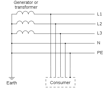
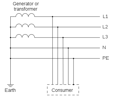
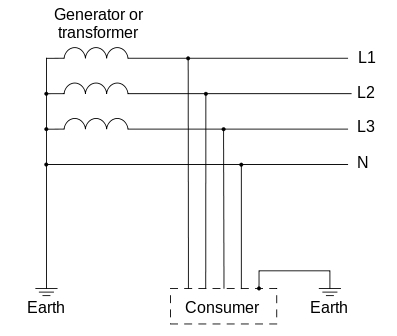
In TN type of earthing system, one of the points of the source side (Generator or Transformer) is connected to earth. This point is usually the star point in a three phase system. The body of the connected electrical device is connected to earth via this earth point on the source side. See fig. below which depicts this:
In above diagram:
PE – Acronym for “Protective Earth” – is the conductor that connects the exposed metallic parts of the consumer’s electrical installation to the ground.
N –Also called Neutral. It is the conductor that connects Star point in a 3 phase system to the earth.
There are three sub-types of TN networks as below:
- TN-S
- TN-C
- TN-C-S
TN-S: In this, separate conductors for Protective Earth (PE) and Neutral run from Consumer’s electrical installation till the source. They are connected together only at the power source.
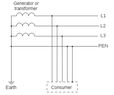
TN-C: In this, there is a combined conductor called PEN (Protective Earth-Neutral) which is connected to earth at the source.
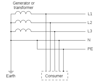
TN-C-S: In this type of earthing, part of the system uses a combined PEN conductor for earthing, whereas for remaining part of the system uses separate conductor for PE and N.
Usually, the combined PEN conductor is used near the source of the system.
TT Network
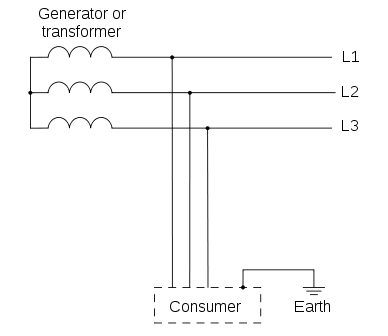
In TT type of earthing system, consumer employs its own local earth connection in the premises, which is independent of any earth connection at source side.
This type of earthing is preferred in telecommunication applications, because this system is free of any high or low frequency noise that comes through neutral wire connected to the equipment.
IT Network
In IT type of earthing system, there is either no connection to earth at all, or it is done via a high impendence earthing connection.
Country Specific Earthing Standards
UK – Uses Protective Multiple Earthing (PME) – which is a form of TN-C-S type of earthing
Australia / New Zealand – Also uses TN-C-S type of earthing know as Multiple Earth Neutral (MEN) system
USA / Canada – Uses TN-C for the feed from Transformer but uses TN-C-S within the structure at customer premises
France / Japan / Denmark – Uses TT type of earthing and customer must make its own arrangement for its own earthing connection
2013/06/06 at 1:06 am #13076Anonymous
GuestVery nice post you got there! Thank you!
2013/06/07 at 8:09 am #13077Spir Georges GHALI
ParticipantDear ;
Refer to this Topic, I would mention to the following points :
– About “ TN-C ” :
The following remark should be also mentioned :
– If the supply of a load is “ 3Ph + N ” and we will use only “ 1 cable of PEN ” between the network and that load, the connection of PEN should be done as follow “ the PEN cable should be firstly connected to the earth point at Load, then to the neutral point ”.
– About “ TN-C-S ” :
It’s mentioned that “ Usually, the combined PEN conductor is used near the source of the system ”, but it’s better to say :
1- For the big networks where the installed power is big or too big, we use TN-C at the 1st and maybe also at the 2nd levels of the network, then we use TN-S.
2- By this way we can decrease the installation’s costs for these 2 levels.
3- We can’t never ever use firstly “ TN-S ” then “ TN-C ”.
– About “ TT ” :
Also, it’s better to add :
– As we can use many independent Earthing points at consumers side only, this system is approximately used all around the world in LV Distribution Networks to supply Housings and buildings.
– About “ IT ” :
We should also mention to the following :
1- If the connection of the transformer is “ ∆ ” ( no neutral point ) we can connect one phase to earth via high impedance.
2- Two main types of “ IT ” that are :
– IT with distributed Neutral
– IT without distributed Neutral.
3- With this Earthing system, It’s absolutely necessary to use special devices called “ Insulation Monitoring Devices ” to detect and indicate any insulation fault .
2013/06/10 at 8:10 am #13073Anonymous
Guesthi dear engineer with this app you can save your money and energy in earthing calculation … this is available on google play for android phone . i thing it is useful for you :)
IEC and BS
2013/12/24 at 10:44 am #13396Anonymous
Guestwhy should the PEN cable be
firstly connected to the earth point at Load, then to the neutral
point?2014/01/01 at 9:27 am #13397Spir Georges GHALI
Participant@shashank said:
why should the PEN cable befirstly connected to the earth point at Load, then to the neutral
point?Dear ;
Ac the ” Protection of person from the Electric chocks ” is the main goal to have an Earthing point in any electrical equipment, the PEN should be connected first
2014/01/01 at 12:39 pm #12713mohamed sleem
ParticipantI’m not sure we can say US uses either TN-C-S or TN-C since the main panel after transformer or generator is connected directly to the earthing through the GEC (grounding electrode conductor).
2014/06/27 at 7:12 pm #13476Anonymous
GuestHi,
Can anybody assist me how to get more than 1K ohms betweens 2 earth pits ?
2014/11/18 at 1:46 pm #13635Anonymous
GuestMy project is IT distribution system, and I am using step down transformer for 230v power loads, my question is , is it necessary to ground the secondary X2? If yes, why we should ground it and what is that system called ( TN or TT). And is it necessary to use PE conductor cable for external load , such as anti condensation heater, single phase fan, etc).
2014/12/02 at 4:57 am #13624denizen360
ParticipantMore information about Earthing
Points to consider in BS 7671 regulations
-
Earth electrodes
BS 7671 lists a wide range of earth electrodes recognised by wiring regulations, including earth rods, earth plates and underground structural metalwork. The single most importance deciding factor in which type of electrode to use is resistance capacity of the soil in the ground. Ideally it should virgin, undisturbed ground, and the effects of soil drying, freezing, and the potential for corrosion, should also be considered, with tests carried out in the worst weather conditions.
-
Sizing of Circuit Protective Conductors
Several factors must be considered when working out the required size of circuit protective conductor. A minimum cross–sectional area of 2.5mm2 copper is necessary for any separate circuit protective conductor, meaning one which is not part of a cable or created by/contained inside a wiring enclosure.
-
Earthing Conductors
Earthing conductors defined by BS 7671 as a protective conductor connecting the main earthing terminal of an installation to an earth electrode must be sized appropriately, especially if partially buried. They must be made from suitable material and protected against corrosion and mechanical damage. The appropriate size is determined in the same way as for a circuit protective conductor, except for with buried earthing conductors, in which case check BS 7671 for further guidelines. In addition, earthing conductors for a TN–C–S supply should not be smaller than the main bonding conductors.
-
Special Locations
These are locations where extra precautions need to be taken. For example PMEs cannot be used for caravans or boats as the combined neutral and protective conductor is not allowed to be connected electrically to any metalwork in them, whilst a TT system is recommended for hazardous areas such as petrol stations, and should be accompanied by the supply of a separate electrode and circuit breaker such as an RCD, in order to ensure that the earthing in the petrol filling area and the PMP earth of the distribution network are separated.
More information about Electrical Earthing
2015/05/05 at 12:46 pm #13674Anonymous
GuestWhat is difference between:
– IT with distributed Neutral
&
– IT without distributed Neutral
in single phase system.2015/08/12 at 5:23 am #13580Anonymous
GuestHi all,
Just join this group. Anyway..from my outstanding, earthing system shall be followed the Country Earthing Standard so no doubt on combination of system….2016/04/16 at 4:54 pm #13775Anonymous
Guestthat’s really helpful.
2016/04/16 at 4:55 pm #13776Anonymous
GuestThank you
that’s great2016/04/19 at 2:33 pm #13779Anonymous
GuestWhat is name of this application?
-
AuthorPosts
- You must be logged in to reply to this topic.
