Home › Electrical Engineering Forum › General Discussion › Thyristor Characteristics
- This topic has 0 replies, 1 voice, and was last updated 11 years, 6 months ago by
 admin.
- AuthorPosts
- 2014/11/14 at 10:50 am #11209
 adminKeymaster
As you may know, Nasir is one of our members who loves to write tutorials, and since last month he’s been sharing a serie of tutorial about semi conductors. Here’s the 5th article of the series.
You can be published on the blog too, just send us a mail.
Thyristor is another electronic component which belongs also belongs to the family of power semiconductor switching devices. It is a bi-stable switch, which means that both its open and closed states are stable and can be controlled successfully whenever desired. This is one of the features which make thyristors more preferable and extensively used in various applications.
Structure of a Thyristor
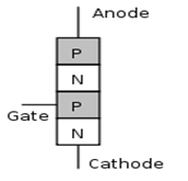
A thyristor is a four layered PNPN structured semiconductor device consisting of three PN junctions. The basic structure of a thyristor can be displayed as follows:

As it can be seen from the structure, the first layer forms a PN junction J1, the second one forms an np junction J2 and the third forms another PN junction J3. The structure also shows three terminals which are:
- Anode
- Cathode
- Gate
For a simple diode we have studied that for conduction to occur, the potential of the anode terminal should be more positive with respect to the cathode.
Now how can be deal with this condition when we have three consecutive junctions for the current to pass through. This can be explained in terms of the three operating modes of the thyristor.
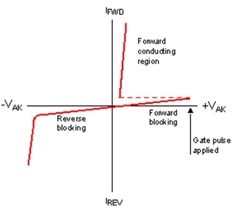
- Forward Blocking or off state condition
- Forward Conducting mode
- Reverse Blocking mode
1) Forward Blocking or Off State Condition
If we make the anode of the thyristor more positive with respect to the cathode as per the required condition, we observe that the PN junction J1 becomes forward biased. The second np junction J2 becomes reverse biased and the third PN junction J3 becomes forward biased. This way the two junctions J1 and J3are in a conducting mode but the middle junction J2 is not.
Due to J2 the current cannot complete its path and hence the thyristor cannot conduct so we call the thyristor to be in the Forward Blocking or off state condition. The leakage current produced in this state is known as the off state current.
2) Forward Conducting Mode
Now if we apply a separate potential at the gate terminal of the thyristors which is connected the positive of the second and third junctions, we can increase the potential of J2 and now instead of it being in a reverse biased mode, J2 can be forward biased due to the increased positive potential applied at the gate terminal.
So this state is known as the avalanche breakdown of the forward conducting mode of the thyristor and the corresponding voltage is known as the forward breakdown voltage.

Control through the gate pulse:
Once the thyristor has received the gate voltage also known as the gate pulse, it will continue to conduct just like a diode since the barrier has been broken and flow of charges can occur feely. This flow can only be interrupted by removing the gate pulse to put the thyristor back to its original state, i.e. the non-conducting mode. Hence we can control the switching of a thyristor through its gate pulse.
The gate pulse can also be used to control advanced switching characteristics, which will be explained in the next tutorials.
3) Reverse blocking Mode
This mode is a simple one and is not widely used. In this state the voltage is applied in the opposite direction i.e. the cathode is at a higher potential than the anode.
Applications of Thyristors
Due to their highly controlled switching states, thyristors are being widely used now a days in many electrical process involving medium to high voltage inputs since the structures of thyristors are built for a medium to high voltage rating.
They are also used in controlling high power electrical applications. Many electrical equipment such as lights, AC motors, welding machines and regulators involve extensive use of Thyristors and they serve as a core part of those electrical machines.
This was all about the basic structure and switching characteristics and applications of the thyristors in electric machinery.
In the next tutorial we will be studying more about the different types of thyristors and on which basis they are divided in various categories. So stay tuned and keep visiting to know on about power semiconductor switching devices.
Thanks for reading me!Nasir.
- AuthorPosts
- You must be logged in to reply to this topic.