Home › Electrical Engineering Forum › General Discussion › Three Way Transfer Switch
- This topic has 2 replies, 2 voices, and was last updated 11 years, 7 months ago by
 Anonymous.
- AuthorPosts
- 2013/10/22 at 3:46 pm #11092
 adminKeymaster
Last but one part of Nasir’s tutorial on Transfer Switches. Enjoy!
Introduction
A Three way transfer switch is used for safe and reliable operation characteristics. Their main function is also the same as many other transfer switches, that is, to provide a continuous and uninterrupted flow of power to the load without producing any damage or fault in the system.
Usually when a transfer switch is used, it acts as a bridge between two power sources. One source is regarded as the “Preferred Source” and the other one is regarded as the “Alternate Source”.
The switch switches its contacts between these two sources, depending upon the availability of power in the preferred source, as the power availability in each of the sources is continuously monitored.
When it senses a power break in its preferred or primary sources, it switches its contacts to the alternate or backup energy source. This was the simple mechanism of a Transfer Switch.
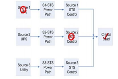
Construction of a three Way transfer switch
But in case of a three way Transfer Switch, we get an additional power source, so that in case both the two sources break up due to some unfortunate reasons, we can still have an uninterrupted supply of power, due to the third redundant source.
So in short we can conclude that the construction of a three way transfer switch is almost more or less similar to a simple two way switch, just with the increment of a third source.
So where a two source switch is designed to survive a single load failure, a three way switch is more efficient and reliable since it survives even two load failures. Although it seems that it is a rare event, but still the probabilities show that its occurrence is not that less common.
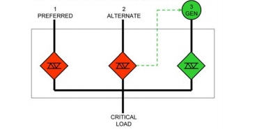
This thing can be shown as follows:

Advantages of a Three Way Transfer Switch
There are several advantages of this setup. First of all this is more safe and reliable and proves as a better option for sensitive loads or loads which require a continuous source of power at all conditions, otherwise they would get damaged or provide extreme losses.
They make your money and investment safe and provide an increased power density. Chances of power failure are almost eliminated and hence a better operation cost can be predicted.
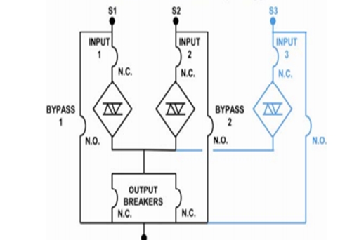
A basic three way transfer switch topology is shown below:

Applications of a Three Way Transfer switch
Due to their increased consistency, these switches find numerous applications in industry as well as for domestic use. These are used with air conditioners, generators, UPS and many other such electrical components which can act as a backup source or would need an urgent alternate power source in case one or the other fails.
They are also used in places where the backup source is urgently needed and is very crucial. A very good example can be a hospital, where such failures cannot be tolerated at any cost.
So another layer of redundancy acts as a very good option over there. This can be shown as follows:

So I hope that now you people must have got a very clear idea of these three way transfer switches and their advantages and applications in everyday life.
In the next article I am going to give a guide on selecting the right transfer switch according to your need and demand.
So stay tuned and keep visiting us for some more informative stuff which is right on its way.
Nasir.2013/11/12 at 8:48 pm #13378AnonymousGuestHi,
I am currently investigating the possibility of using 2 or 3 x single phase capacitor banks in a PV solar installation to store energy after the inverter. Considering that most households use a 60A rated main switch, I am very interested to know about the rating and choice of the three way transfer switch for this purpose?
Primary – AC via Capacitor banks
Secondary 1 – DC via Inverter
Secondary 2 – AC via Utility Grid
Thank you.
2014/09/24 at 6:56 pm #13602AnonymousGuestI love your blog.. very nice colors & theme. Did you make this website yourself or did you
hire someone to do it for you? Plz answer back as I’m looking
to design my own blog and would like to know where u got this
from. many thanks - AuthorPosts
- You must be logged in to reply to this topic.