Home › Electrical Engineering Forum › General Discussion › Setting up a Fuse Box and calculating loads
- This topic has 1 reply, 2 voices, and was last updated 10 years, 5 months ago by
Anonymous.
-
AuthorPosts
-
2014/07/03 at 4:07 pm #11099
admin
KeymasterLast time, we told you about Andrei. He sent us an article again to participate in the blog. Remember you can do the same by sending us a mail.
Introduction
Some might consider setting up a fuse box for a residential location a pretty simple task. 16 A circuit breaker and 2.5mm² conductor for wall sockets, 10 A circuit breaker and 1.5mm² conductor for lighting circuit, not very complicated. I should say the above values are for European 230V single phase circuits.
But what if we had to distribute electricity to a workshop or a place that has different than usual loads like motors or power tools? Let’s have a look at how we can setup this circuit and the fuse box for it.
Calculating loads
Like with any other circuit we need to determine the total current required to power it. For our workshop example, most single phase power tools and equipment will be under 2000W and this is the safest maximum load to have on a 230V line running continuously. Above this power most likely the equipment will need 3 phase circuit.
We know the formula to calculate the current for low power equipment like lamps is IN=
with U=230V and cosϕ depends on the load type. For resistive loads such as heaters, incandescent lamps, cosϕ=1, for fluorescent lamps with internal compensation cosϕ=0.8-0.95. You have to keep in mind that for fluorescent lamps Pi=Plamp + Pbalast.
For motors, high power single phase loads, the formula is a little different : IN=
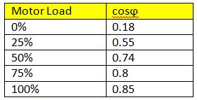
where η is efficiency. If you don’t know the efficiency you can use a value of 0.8. The below table offers an estimation of cosϕ for asynchronous motors:
Dimensioning circuits and Circuit breakers
It is a good practice to keep loads under 2kW on each independently fused circuit but with motors and high current machinery we need to be careful what kind of circuit breaker we choose because many motors on start will draw a lot more current than the nominal value and this can cause the breaker to trip.
There are 3 main types of circuit breakers or MCBs marked with the letters B,C and D. These differ in the instantaneous tripping current value with B having a value between 3 times and 5 times the nominal current, C between 5 times and 10 times the nominal current and D between 10 times and 20 times. Depending on motor you might need a C or D circuit breaker.
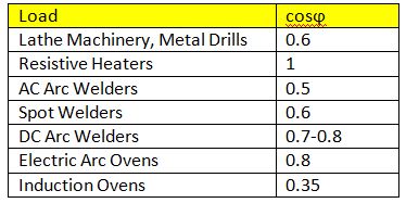
According to IEC 60364-4-41 every wall socket circuit must be protected by RCD with a high sensitivity <=30mA. It is recommended not to have more than 8 sockets on the same circuit. For places like workshops, restaurant kitchens, laundry rooms I usually install a separate fuse box so that the circuit breakers are closer to the equipment. Once we have calculated the current necessary for all circuits at the location the sum of these current values will determine the wire section between the main fuse box and the remote one. Please refer to the next table for additional estimation of cosϕ values for common electrical equipment. To calculate wire section there is a very good online tool who can help you calculate it for NEC or IEC standards: http://www.cablesizer.com/
With all the loads distributed evenly on the new circuits and all the circuits protected accordingly with MCBs for lighting and RCBOs for wall sockets it is important to note that the MCBs role is to protect the circuit. The current rating should be the next step above the current drawn by load. So if load is 14A a MCB of 16A should be chosen along with the proper wire section for the circuit. The circuit breaker must protect this wire from overheating and potentially causing a fire or breaking the circuit.
In low voltage residential installations distances are small enough to not pose problems with voltage drops along the lines but in my experience I have found many problems with earth connection when setting up a new fuse box.
Another common problem was failure to distribute the load on all 3 phases at the general fuse box but this is a subject for another article. As we can see this subject is very vast and I will discuss more about it in future articles so be sure to check back in.
Thank you for reading!
Andrei.
2014/08/13 at 7:06 pm #13519Anonymous
GuestThanks for this information . For air condition or split unit loads how can I convert from ( BTU ) to ( KW ) ?
-
AuthorPosts
- You must be logged in to reply to this topic.

