Home › Electrical Engineering Forum › General Discussion › Reverse Conducting and Gate Turn off Thyristors
- This topic has 0 replies, 1 voice, and was last updated 10 years, 3 months ago by
admin.
-
AuthorPosts
-
2014/12/08 at 10:18 am #11216
admin
KeymasterNew article from Nasir’s series of articles on Thyristors. You can also check the previous ones if you’ve missed them.
Introduction
Up till now we have become pretty much familiar with the properties, types and uses of thyristors. We came to know their diverse applications in the field of electrical technology. Different properties, operating characteristics, types, specifications and advantages of thyristors have been discussed and compared with the diodes, which are also a type of Power Semiconductor Switching devices we discussed.
Now this article brings a conclusion to our topic of power semiconductor switching devices, by discussing the last of our details of thyristors, which I hope would be an essential addition to your knowledge of power semiconductor switching devices.
Freewheeling diode analogy
Among the vast variety of thyristors we have discussed, we came to know that SCRs are the most commonly used type in our daily life and its electrical structure and conducing properties are the same as the common thyristor structure we discussed earlier.
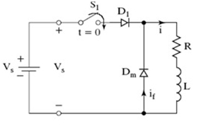
Now if you remember that while discussing a diode with an inductive load, we said that an inductor stores energy and when the conduction is switched off, it releases its stored energy. In order to provide an alternate path for the voltage to flow so that it does not damage the circuitry we added another diode in parallel with the inductor so that the current could pass through it.
This diode was called a freewheeling diode and is shown in the circuit below:
Here D1 is our regular diode and Dm is our freewheeling diode which is connected across the inductor L.
Reverse Conducting Thyristors
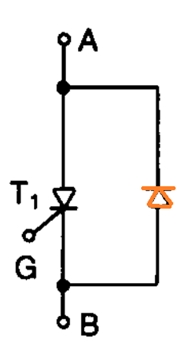
Now the question that might be arising in your mind is that how am I going to relate this freewheeling diode with a reverse conducting thyristor? The answer to this question is pretty simple. The same way when an inductive load is connected, we connect an anti-parallel diode across the SCR to provide an alternate path for the flow of current.
This alternate path like in case of the freewheeling diode has the following advantages:
- It prevents our circuitry from damaging.
- It improves the turn off requirements of the commutation circuit.
The basic structure of a reverse conducting thyristor is shown in the figure below:
Here the reverse conducting diode is indicated by the red mark. This diode is capable of clamping 1 to 2 volts of the reverse blocking voltage of the SCR across which it is connected in anti-parallel direction. However before this reverse voltage of the inductor attains a steady state value, it can reach higher values up to 20 to 30 volts.
Gate Turn Off thyristor
A gate turn off thyristor is more or less similar to an SCR that we have studied before except for the fact that its off signal can also be controlled. A GTO can be switched on by applying the positive signal at the gate terminal and hence when a negative signal is applied the GTO is turned off.
Conclusion
So these were the other two commonly used types of thyristors which have many advantages and diverse use in electrical related applications due to their controlled triggering and operating characteristics. Other types are also a combination of these types and can be used according to the requirement of the user.
Thanks for reading,
Nasir.
-
AuthorPosts
- You must be logged in to reply to this topic.

