Home › Electrical Engineering Forum › General Discussion › RC and RL Loaded Diodes
- This topic has 0 replies, 1 voice, and was last updated 10 years, 2 months ago by
admin.
-
AuthorPosts
-
2014/12/11 at 1:44 pm #11218
admin
KeymasterToday, one of our loyal members is dedicating an article to explain the behavior of diodes to various kinds of loads.
Introduction
Up till now we have studied quite a lot about the basics of diodes. Taking a quick revision, we came to know that how do semiconductor power diodes acts as switches, how their electrical properties change and how their current and voltage properties vary when they are connected in series or in parallel with each other.
These were some of the major characteristics of diode that we came to study up till now. One thing that would have knocked the mind of you guys would be that how would a diode react to a load attached to it. What kind of outputs can we get through the loads?
Well the answers to these questions are pretty simple…
Simple Resistive Loads
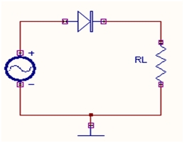
The simplest kind of load that we can consider to understand the behavior of a diode is a resistor connected in series with a diode.
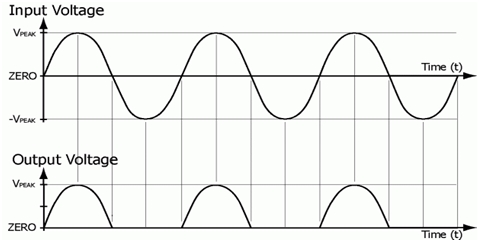
As we know that the diode conducts during the positive half cycle and acts as an open switch during the negative half cycle. So let us suppose that we gave a sinusoidal wave at the input as shown in the figure. At the output we will only get the positive half of the wave and nothing during the negative half.
The resultant waveform will look something like this:
This type of configuration is also known as a half wave rectifier, since the diode only rectifies half of the wave.
Usage of a Half Wave Rectifier
Half Wave rectifiers are usually used in AC to DC conversion of voltages since we get a unidirectional positive half of the input wave at the output.
Resistive and Capacitive Loads
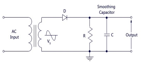
Now what would happen if we connect a capacitor in parallel with a resistor, shown as follows:
In the output of the half wave rectifier above, we also observe some bumps, since it is not quite smooth. In order to eliminate these bumps and obtain a smooth output waveform, we have to make the use of a capacitor.
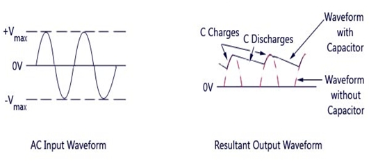
We know that a capacitor is an energy storing device. So during the positive half cycle of the waveform when the diode is conducting, the capacitor stores the energy. When the diode ceases to conduct during the negative half cycle, the capacitor starts to discharge and releases its stored energy, such that the waveforms doesn’t ceases abruptly but rather smoothly due to the discharge of the stored energy.
This process can be viewed below:
Resistive and Inductive Load
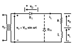
When an inductor is connected in series with a resistive loaded diode, we observe that the inductor being an energy storing element also stores energy and opposes the change of direction of the current.
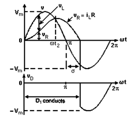
During the interval of the positive half cycle from 0 to pi, the diode conducts and the inductor stores energy. But when the diodes tends to stop the conduction process from pi to pi/2, the inductor opposes and releases its energy, such that instead of ceasing to conduct at pi, the diodes conducts for a little more time before turning off.
The output waveform thus visualized is as follows:
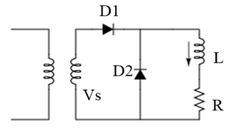
In order for the released energy of the inductor to discharge, we also attach a freewheeling diode in the following way:
This diode provides an alternate path for the flow of the stored energy within the inductor.
So now since you are familiar with the behavior of diode and its load in different cases, I hope you will be able to deal with switching behavior of diode and its uses in different forms.
Another interesting semiconductor power switching device is on its way in the next articles. So stay tuned and keep yourself updated on all our tech stuff.
Nasir. -
AuthorPosts
- You must be logged in to reply to this topic.
