Home › Electrical Engineering Forum › General Discussion › Power Factor In Depth
- This topic has 1 reply, 2 voices, and was last updated 12 years ago by
Spir Georges GHALI.
-
AuthorPosts
-
2013/02/07 at 2:19 pm #10962
Steven Mill
ParticipantIn this article we shall have detailed discussion on something that is very common for Electrical Engineers and you must know about it “Power Factor”. Here we will deeply examine what we actually mean by the term Power Factor and why it is so important in our field.
We will have a look on the following:
- Definition of Power Factor (simple)
- Leading and Lagging Power Factor
- Active Power and Reactive Power
- Why so IMPORTANT
- Distortion Factor and Displacement Factor
Definition Of Power Factor
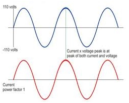
As we all know Power Factor is defined as the cosine of angle between voltage and current wave. Thus it can only take value between 0 and 1. One when both voltage and current are inn phase and zero we they are at right angle to each other. This is the delimitation of Power factor assuming both voltage and current are pure sinusoidal quantities.
Leading and Lagging Power Factor
For power factor measurement we take the voltage phaser as our reference and see whether the current phaser is leading or lagging the voltage. If current is leading we say that Power Factor of the system is leading and likewise for other case.
Current in capacitor leads voltage so Power Factor is leading n case of capacitive loads.
For Inductive loads current lags the voltage so Power Factor is lagging for them.
For pure resistive load current and voltage are in phase thus Power factor is unity.
Note that inductance and capacitance have opposing effect on each other i.e we can add capacitance to our system to minimize inductance and vice versa.
Active Power and Reactive Power
This is something an electrical engineer must be very clear about. Active Power also called Real Power is mathematically equals to product of RMS values of voltage and current phase multiplied by cosine f angle between them.
Active Power=V(rms)I(rms)cos(angle between V and I)
Reactive or Imaginary Power is calculated in the same way as Active Power but here we have to use sine function instead of cosine.
Active Power=V(rms)I(rms)sin(angle between V and I)
Apart from knowing how to calculate we must know the physical meaning of these quantities. Active Power is the source of the actual work done by the system or load, In other words the useful work done by electrical supply or the useful power supplied by electricity is Active Power. This is the type of power that ultimately transforms into some other useful form like heat or mechanical energy.
What about Reactive Power than? Why it is here if it is of no use?. Actually Reactive Power is drawn by the capacitance or inductance in the system. If any of these to characteristics of system is significant system will draw a considerable amount of Reactive Power.
Actually what happen is, both inductor and capacitor (pure) are lossless elements means that they don’t consume any power they only cause voltage drop across themselves. They only absorb power from the source and release it after wards. Thus Reactive power oscillates or moves to and forth in the circuit without doing any useful work.
But note that our source has to provide that required amount of Reactive Power depending upon reactance of the system to keep things running properly.
Power Factor, Why So Important?
After the discussion above we are in position to understand the importance of Power factor in electrical systems. From above debate we can conclude that “It is desirable to maximize Active Power delivered by the system and minimize the other type of power”.
As we said that we want to maximize Active Power and minimize Reactive. It should be clear to you from mathematical relations given above that for us to accomplish required task, Power Factor must be close to unity.
That’s why you would have heard commonly that we want to have Power Factor as closer to unity as possible, but it is practically not possible in actual electrical systems due to intrinsic inductance and capacitance of the system.
We should know that our transmission lines have both natural inductance and capacitance and we have to employ techniques to bring Power Factor to the desired level. It is another topic that discuss effect of capacitance and inductance on power line and how we apply power factor correction techniques to rectify our problem.
Power Factor (Practically)
Why we say practically? You will understand in a while.
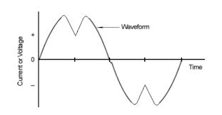
As we all know our electrical loads are full of electronic equipment and you should know that electronic loads draw no linear current i.e. the current drawn by such loads is not sinusoidal. In technical terms we say that they introduce harmonics in the system.
So how to define Power Factor now where we don’t have a pure sine wave of current.
Distortion and Displacement Factor
In this case we define Power Factor as the Product of two quantities distortion and displacement factor.Power Factor=Distortion factor*Displacement factor
Before moving further note that through Fourier analysis a non-sinusoidal signal can be decomposed into sum of sinusoids called harmonics.
Displacement factor is cosine of the angle between the fundamental component of both current and voltage signal.
Distortion factor exhibits level of distortion in signal from pure sine wave.Note for linear loads Distortion factor becomes equal to unity leaving behind only displacement factor therefore for linear loads we define Power Factor as given in beginning of the article.
For this article, we chose to go back to the basics. What’s your opinion on this explanation of Power Factor?
2013/02/21 at 10:23 am #13092Spir Georges GHALI
ParticipantDear Mr. Steven ;
First, it’s a good subject to be discussed but certainly not the principal basics as mentioned, because all Electrical Engineers should absolutely know it.
Let me please mention to the following points:
Leading and Lagging Power Factor :
- When mentioned “ Voltage phaser or Current phaser ” that means “ Voltage Vector or Current Vector ” .
- When you say “ we add capacitance to our system to minimize inductance and vice versa ”, you certainly mean that we add the capacitance to have a capacitive current that will minimize the inductive current ”.
Active Power and Reactive Power :
- The 2 formulas are mentioned to the “ Active Power ” where the 2nd should be :
“ Reactive Power : V(rms)I(rms)sin(angle between V and I) ”
- It’s mentioned that “ both inductor and capacitor (pure) are lossless elements means that they don’t consume any power they only cause voltage drop across themselves”, but sorry to say : electrically it’s not right, because when there’s a drop voltage, that means there’s a current runs in the circuit, and if there’s a current that means there’s a Power’s consumption. By another wards:
- All “ pure Capacitive or pure Inductive loads consume a Reactive Power ”.
- The Reactive Power is a kind of power without obtaining a useful work.
- It’s mentioned also that “ They only absorb power from the source and release it after wards ” and “ Thus Reactive power oscillates or moves to and forth in the circuit … ”, but sorry to say : electrically it’s not right, they absorb ( consume ) power but they don’t release it, and also the absorbed Reactive Power doesn’t oscillate or move to and forth in the circuit.
Power Factor (Practically) :
To be more clear, the relation between the “ Cos ϕ ” ( Power Factor for the Fundamental Voltage and Current ) and the Power Factor for Network containing Harmonics ( Polluted Network ) is done by the following formula :
Power Factor = Cos φ / √(1+THD I²)
Where the “ THD I ” is the Total Harmonic Distortion of Current.
So, relative to your formula the Distortion Factor is : 1/√(1+THD I²)
-
AuthorPosts
- You must be logged in to reply to this topic.

