Home › Electrical Engineering Forum › General Discussion › Multilevel Inverter Topologies
- This topic has 1 reply, 2 voices, and was last updated 12 years, 4 months ago by
 Anonymous.
- AuthorPosts
- 2013/12/03 at 1:30 pm #11111
 adminKeymaster
Check the latest article of Nasir (one of our members) from his tutorial about inverters.
Owing to the recent popularity and immense industrial usage of multilevel inverters, a lot of research is going on in the field of multilevel inverter topologies. All these topologies have various applications along with their inherent limitations.
There are two methods of controlling multilevel inverters:
- PWM Control (allows variations in output voltage)
- Line Frequency Control (does not allow variation in output voltage)

Three of the very basic and might I say the initial topologies are:
Cascaded H-Bridge Multilevel Inverters
- They consist of switching devices and diodes arranged in an H-bridge configuration.
- Changing the pattern of switches give different voltage levels.
- The usual inverter uses separate DC sources but another topology using only single DC source is also available.
Advantages:
- We get same switching frequencies for all the switches.
- Modular structure is easier to analyze.
Disadvantages:
- Separate DC sources are required.

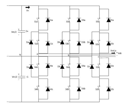
Diode Clamped Inverters
- Diode clamped inverters are also known as neutral point inverters.
- They aim at converting the DC source voltage into capacitor voltage.
- For n levels, n-1 consecutive switches from a single phase must be turned on.
- For n levels, n-1 capacitors are required.
Advantages:
- Low cost and less components due to less number of capacitors.
- Can be operated on SDCS.
Disadvantages:
- For more than three levels, the charge balance gets disturbed.
- Output voltage gets limited.
Capacitor Clamped Inverters
- Also known as flying capacitor inverters (because they float with respect to earth’s potential), they use capacitors as clamping devices instead of diodes.
- The clamping capacitors have to be pre-charged before using them in the inverter.
- Only one switch out of each pair has to be in the on state necessarily to ensure the balanced configuration.
- There are redundant states of switches to guarantee balanced voltages in floating capacitors.
Advantages:
- Each branch can be analyzed independently.
Disadvantages:
- Pre-charging capacitors is difficult.
Other Topologies
Numerous other topologies have been proposed which aim at combining the benefits of these basic topologies or removing their disadvantages. Few of the relatively popular ones are mentioned:
- Generalized P2-cell Multilevel Inverter
Abbreviated as GMLI, this cell has the capability to self- balance, which the previous topologies lacked. This comes really handy while delivering active power. GMLI has two voltage level cells. Each contains two pairs of diodes and switches and one capacitor in each cell. All these cells are connected in a triangle.
- Reversing Voltage Multilevel Inverter
RVMLI is a relatively less popular topology. It first gives only half wave by sending only positive value and then by using a converter, it changes it into negative value half way through to give out a complete sine wave.

Modular Multilevel Inverter
Modular multilevel is a new topology and as its name suggests, its design strategy involves modules. Modular approach has been accepted as an easier and better approach by many schools. Every module consists of half bridge.
Which of the topologies is the best depends, upon place where you use it and you requirements. There are many types of multi-level inverters, designed according to different applications and their uses. Some of the most important ones, which are widely used now a days will be discussed in the next article.
Nasir.
2014/01/01 at 1:07 pm #12714AnonymousGuestAssallamoallankum, I have been reading articles written by different members but i am sorry to say that the writer do justice with neither reader nor the article itself because most of the requisite details to under stand what the author want to convey to reader are found missing. I hope, members will not mind it . It is a simple suggestion so that in future when any one who will write an article on any electrical top will definitely add all details, to it make more beneficial for the reader .
Thanks and best regards,
Nazir Ahmad
Ex-chief Engineering
Continental Biscuits Ltd. - AuthorPosts
- You must be logged in to reply to this topic.