Home › Electrical Engineering Forum › General Discussion › Measuring resistance with Ohmmeter
- This topic has 0 replies, 1 voice, and was last updated 9 years, 10 months ago by
admin.
-
AuthorPosts
-
2015/04/20 at 9:49 am #11246
admin
Keymaster
New article from the series of tutorial that Nasir – one of our most prolific members – wrote on measuring instruments. This time he focuses on ohmmeter.You too can send us articles. Just send a mail to the team!
What is an Ohmmeter?
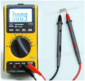
Ohmmeter is another interesting measuring instrument that is used for measuring the resistance between any two points in the circuit. It is of extreme importance and is widely used in circuit analysis and debugging nowadays.
As we know that the units of resistance are ohms, so we know that where the name of this device comes from, as it measures the ohms between any two points in the circuit.
How does an ohmmeter measure resistance?
For measuring the amount of resistance in the circuit, the first and foremost thing that needs to be checked is that the ohmmeter should have its own built in voltage supply. This can be in the form of a small battery, typically 1.5 volts used for normal everyday purposes, but different ratings are also available.
The need for a built in voltage supply arises from the fact that for measuring the resistance, the ohmmeter passes the current through that place and then measures the drop in voltage that is the resistance through the output value of the current.
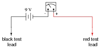
For measuring the unknown resistance, the voltage supply of the circuit is first turned off and then the two probes of the ohmmeter are connected to the two points between which the value of resistance needs to be measured.
The red probe is connected to the positive side of the circuit and the black probe is connected to the ground side of the circuit, as shown below:
When the ohmmeter is turned on, the current from the battery passes through the circuit and the voltage drop or resistance i.e. the opposition to the electron flow is measured.
Types of ohmmeter
Ohmmeters are available in two forms i.e. the digital ohmmeter and the analogue ohmmeter. The digital ohmmeter displays the value of unknown resistance digitally, in the form of numeric digits. And the analogue ohmmeter displaces the value through a moving needed on a marked scale. When the current passing through the circuit is maximum with respect to the input voltage, the resistance is said to be minimum, according to ohms law.
Vice versa, when the current is minimum the resistance is maximum and the needle moves to the extreme left of the scale to indicate the maximum value of ohms, as shown in the figure below:
Ohmmeter can also be used to measure the variable resistance of a variable resistor.
Calibrating your Ohmmeter
In order to check if your measuring device is working correctly, just connect the two probes of the ohmmeter with each other.
This should show the minimum level of resistance, which is ideally zero and can practically be a few micro or milliohms.
Applications of ohmmeter
- These are being widely used now a days to check circuit continuity, i.e. if enough current is flowing through the circuit or there is infinite resistance between two points and the circuit id disconnected.
- They are also used as laboratory testing equipment in different experiments and for teaching purposes.
- They are quite useful in debugging small chips like printed circuit boards and other stuff which needs to be implemented in sensitive equipment.
Conclusion
This was all about ohmmeters for now. I hope this article was useful and helped you in understanding about the working of an ohmmeter.
I have a couple of more measuring devices for you as well. In order to know more about these measuring instruments, keep visiting the blog.
Thanks for reading my articles,
Nasir. -
AuthorPosts
- You must be logged in to reply to this topic.


