Home › Electrical Engineering Forum › General Discussion › Lightning & Surge protection
- This topic has 46 replies, 10 voices, and was last updated 7 years, 7 months ago by
Horence.
-
AuthorPosts
-
2011/02/21 at 7:15 am #11839
Anonymous
Guesthi
could you help me for finding INDELECT software for finding the best place for installing prevectron?2011/03/01 at 12:06 pm #11862Chris2011
ParticipantRatha said:
Hello, I am Ratha.
I would very much appreciate if the group could share with me the information of Installation of Earthing (Grounding) for Direct Lightning Protection system. And the installation of Down Conductor.
Thank you very much.
you can send e-mail to sales03@fatech-surge-protection.com, they are professional on provide lightning and surge protection proposal, and grounding proposal.
2011/04/14 at 12:30 pm #11958admin
KeymasterHi
Isn't the surge protective philosophie concerning T2 arresters described in Wiki-EIG a little bit old -fashioned?
http://www.electrical-installation.org/wiki/Selection_of_a_Type_2_SPD
I understand that it is coming from the time when France had own standard which knew only todays T2 arresters and they were suggested to be choosen concerning by risk of lightning (and by more valuable equipment).
Today, when international standard uses 'german' (my term) approach – T1, T2, T3 arresters – I do not see the reason to split T2 arresters (which are mainly varistors) into so many different levels. The Up of smaller varistors is mainly lower only for the reason that Up is always measured by In, so by the same surge current the actual Ures is the same , or by same cases – more powerful arresters have even lower Ures thah the smaller ones.
There is not significant price difference either (at least on our market) between T2 arresters having Imax 40, 20, 15 , or 5 kA.
T2 arresters having Imax 65 kA are today sold under label T1+2 with Iimp =7kA
Price depends more from how famous is the brand name of the producer or of his activity on the market.
I find that there is enough to have one standard T2 arrester 40/20kA and in the last end to use T3 arrester.
Btw. If I read the definition of the “Lighting Protection Zones” in EN 62 305 , than I understand, that LPZ 3 requires defenitely screening of the zone. So – it means that there is no sense to install T3 arrester into distribution board if the device to be protected is located not in the same DB but situated somewhere in distance and feeded via normal PVC cable without screen?
(of course – installation T3 there makes not the situation worse)
PS
What You as specialists think about so called 'T1+2' arresters, which itself are only a little bit more powerful varistors.
Is their effect really comparable with devices where 2 physically different devices (spark gap and varistor) are mounted beside each other (sometimes on the same base only, sometimes into the same housing)?
2011/09/15 at 2:21 pm #12515Anonymous
GuestLet me know about your works to enable us to proposed our products
2011/10/31 at 3:13 am #12609Anonymous
GuestHi..
Thanks for info thats you give…this relay helf me…2012/01/12 at 9:09 pm #12822vinodgomkar
ParticipantFrancois said:
after 15 years of experience I feel important to come back to some basics
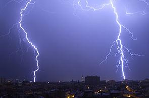
[caption id="attachment_502" align="alignright" width="207" caption="city lightning"]
[/caption]
Protection against the destructive lightning effects should be considered globally.To avoid the fire of a building we will use the “external” lightning protection system such as lightning conductor or meshed cage.
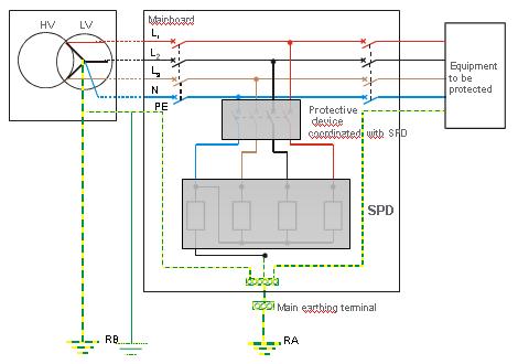
In the same way, we will install Surge Arrester or surge protector (also called SPD, Surge Protective Device) in the Electrical main board to protect sensitive electrical equipment against surges generated by lightning strokes fell close or directly on the building.
15 years of experience in the field of surge protection lead me to write that the technology and understanding of phenomena has evolved. However, further issues have to be clarified …
One of the main issues to clarify in my opinion is the behaviour of the surge arrester, “surge protector“ (SPD) implemented in an electrical panel. Today many designers think it is enough to connect a surge protector (SPD) on the grid so that it provides protection against surges caused by lightning effects. Of course, this role is the main function of the surge protector (SPD). Nevertheless we have to consider its integrity in operation, outside a period of storm, mainly during the permanent fault on the electrical power network.
In other words, a surge protector (SPD) must be coordinated with a safety protective device that disconnects from the network when the SPD is in short circuit. The cause of this development are mainly short-circuit failure of the neutral or permanent overvoltage which unfortunately appear on the electrical networks (from current or renewable energy)
Surge protection can be effective and safe if this association is coordinated with its protective device (Circuit breaker or fuse). For example, surge protector (SPD) with nominal current discharge In=5kA should be associated with a circuit breaker C curve – 20A, breaking capacity consistent with Isc of the electrical installation from (6KA to 25kA)
by the way, you can visit this site : Interesting web site dealing with the lightning phenomena in the several fields as meteorology, medical, scientific and technical – in French and English languages
Didier Mignardot
2012/01/12 at 9:11 pm #12823vinodgomkar
ParticipantLightning & Surge protection is the very sensetive equipment to save the auxilaries from lighting strokes
2012/04/15 at 10:23 am #12911syed bilal mohsin ali
Participanthow can we select surge protect device in low voltage panels.
2012/04/16 at 8:12 am #12913olivier bouilliez
ParticipantSurge protection devices have to be selected after a complete study of the installation .
You will find good documents in
http://www2.schneider-electric.com/sites/corporate/en/customers/designers/designers.page
Download the following : CT 179 – LV Surges and Surge Arresters – LV Insulation Co-ordination
2012/08/29 at 10:01 am #13176Anonymous
GuestI recently came across your blog and have been reading along. I thought I would leave my first comment. I don’t know what to say except that I have enjoyed reading. Nice blog. I will keep visiting this blog very often.
Joannah2012/08/29 at 10:06 am #13177Anonymous
GuestI would very much appreciate if the group could share with me the information of Installation of Earthing (Grounding) for Direct Lightning Protection system. And the installation of Down Conductor.
2012/08/29 at 1:18 pm #13178Anonymous
GuestThank you for your great comment
Didier Mignardot
2012/08/29 at 1:50 pm #13179Anonymous
GuestLot of pieces of information are included into the standard IEC 62305-4 edition 2 2010 01 chapter 5 “Earthing an bonding with clear explanations and charts(pages 21 to 29).
Didier M
2012/08/30 at 6:52 am #13183Anonymous
GuestI feel this is one of the so much vital information for me. And i am happy studying your article. However should observation on some general issues, The web site taste is ideal, the articles is actually great.
2013/02/24 at 10:01 am #13098Spir Georges GHALI
Participant@guest said:
i am studying short circuit calculation for power systems.pls send me the data for designing and selection of protective devices for scDear ;
As we know all, at the end of life of any SPD a short circuit is happened between “ one phase or more ” and the “ earth point ”, therefor the SPD’s supplying should absolutely be disconnected, for this reason, we have 2 products can be used to disconnect the supplying once that short circuit happen, that are :
- Circuit Breakers “ C.B. ”: 2 ranges can be used “ MCB & MCCB ”, and it will better if they have only a Magnetic Protection.
- Fuses : they should be of “ Network Protection ” range.
After defining the used Earthing System for the network, and the SPD’s main specifications especially : the Number of Poles & the prospective Discharging Current, the more important specifications of the Protective Devices that should be defined are the following :
- Number of Poles : it should be exactly the same as the number of poles of SPD. Noting that if the SPD has a Neutral pole the protective device should absolutely has it.
- Nominal Current for C. B. : if they have only a Magnetic Protection, the usable Nominal Current are “ 25, 40, 63, 80, 100, 125, 160A ”, where the choice will be done depending on the discharge current’s value, as well as this value increase the nominal current’s value will be increased, but if C.B. have also a Thermal Protection, we define first the value of that protection ( see bellow ), and the Nominal Current will be defined accordingly ( depending on the manufactures’ ranges ).
- Breaking Capacities : this value can be defined after knowing the Maximum Short Circuit Current at the installation’s point, where “ Breaking Capacity ≥ Iscmax ”. Noting that :
- The values of the Maximum Short Circuit Currents are normally calculated when we design any Electric Panel ( Electric Board ).
- If the SPD’s number of poles is “ 3P with or without Neutral ” the “ Iscmax ” is for a short circuit between “ 3 phases ”, but if the SPD is “ 1P+N ” the “ Iscmax ” is for a short circuit between “ 1 phase & neutral ”.
- Magnetic Sitting ( Short-time Sitting ) for Circuit Breakers :as at the end of life of SPD a short circuit between “ one phase or more and the earth point ” called an Earth Faull, we define the value of this protection depending on the CB’s type as follow :
- “ MCB ” : the type of this protection should be “ C curve ”.
- “ MCCB ” : the value of this protection will be defined after knowing the Earth Fault Current at the installation’s point, where “ Magnetic Protection < Id ”.
We define the value of the Thermal Protection either for Fuses or Circuit Breakers if they have also this protection ( called also Long-time Protection ) as follow :
- Thermal Sitting ( Long-time Sitting ) : if possible, we don’t need for C.B. an adjustable Thermal Protection, the usable settings are “ 20, 25, 32, 40, 50, 63, 80, 100, 125, and 160A ”, and the choice will be done depending on the discharging current’s value, as well as this value increase the sitting value will be increased. For example : for discharging current “ 5kA ” we can use “ 20 or 25A ”, and for “ 65kA ” we can use “ 125A ”.
Rem. 1 : as the SDP should be replaced at the end of life, therefor we should know when should be, to know that we have 2 possibilities :
- By regular check-up of each installed SDP especially during the season of Lightning Strikes.
- By using SPDs equipped with an “ Auxiliary Contact ” that change his state at the end of life.
Rem. 2 : some manufactures produce SPDs equipped with suitable “ Disconnectors ”, so, no need to use with those SPD’s any protective devices.
Rem. 3 : if the SPD has “ 2P ” ( 2 phases ), the same Breaking Capacity’s value for “ 3P ” can be used.
-
AuthorPosts
- You must be logged in to reply to this topic.


