Home › Electrical Engineering Forum › General Discussion › Introduction to Second Order Systems
- This topic has 1 reply, 2 voices, and was last updated 11 years, 10 months ago by
 Anonymous.
- AuthorPosts
- 2014/04/02 at 3:05 pm #11150
 adminKeymaster
Next article of Nasir from his tutorial on Control Systems.
Introduction
As we discussed earlier we have two methods of analyzing the working and functioning of a control system named as:
- Time domain analysis
- Frequency domain analysis
The time domain analyzes the functioning of the system on basis of time. This analysis can only be applied when nature of input plus mathematical model of the control system is known. Expressing the main input signals is not an easy task and cannot be determined by simple equations. There are two components of any system’s time response, which are:
- Transient response
- Steady state response
In order to judge the functioning and behavior of a system, typical and standard test signals are used. The characteristics of an input signal are constant acceleration, constant velocity, a sudden change or a sudden shock. We have already discussed four types of test signals i.e.
- Impulse
- Step
- Ramp
- Parabolic
We already discussed first order systems in detail in the previous article. It said that the system whose input-output equation is a first order differential equation is called a first order system. In this article we will be focusing on second order systems.
Second Order Systems

The order of a differential equation is the highest degree of derivative present in that equation. A system whose input-output equation is a second order differential equation is called Second Order System.
There are a number of factors that make second order systems important. They are simple and exhibit oscillations and overshoot. Higher order systems are based on second order systems. In case of mechanical second order systems, energy is stored in the form of inertia whereas in case of electrical systems, energy can be stored in a capacitor or inductor.
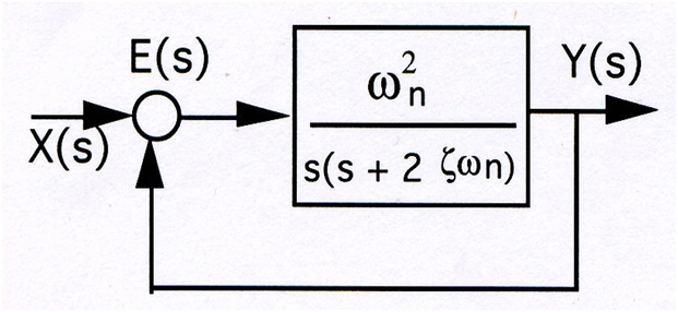
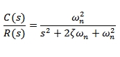
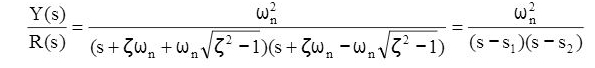
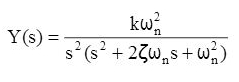
Standard form of second order system is given by:

Where:
- ωn Is the natural frequency
 is the damping ratio
- If 0< <1, system is named as Damped System
- If < =1, system is named as Critically Damped System
- If < >1, system is named as Over Damped System
Response of a Second order system
We analyze the responses in second order systems in undamped, under damped, critically damped and over damped cases. Let us have a look on these:
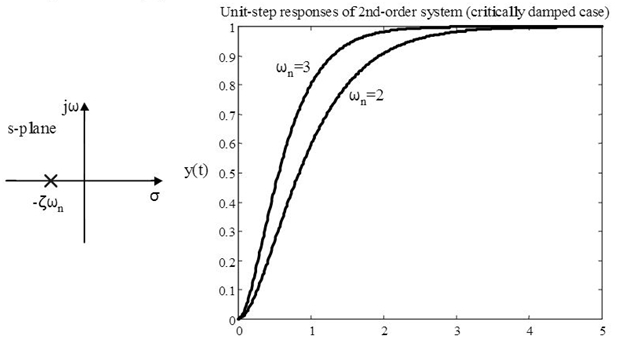
- 1. Step response of Second-order systems:
Critically Damped Case: (
=1)
Two poles are equal. That means:

In a unit step input, we have:
And output is:

Steady-state error: e (∞) = 0
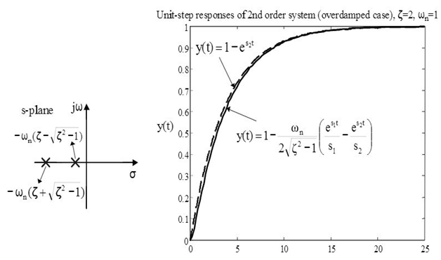
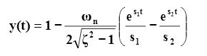
Over Damped case: (
> 1)
We can write the transfer function of a second-order system by factoring the denominator as:

Taking the inverse Laplace transform yields the time response:

The unit-step time response is:

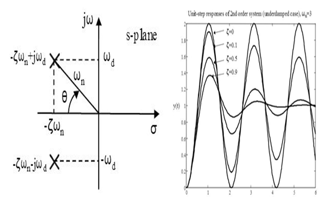
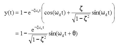
Damped case: (
< 1)
For a damped case in which 0 < < 1 time response is given by:


- 1. Ramp response of a second-order system:
Again we have 3 cases here that are:
= 1, critically damped case > 1, over damped case0 <
< 1, under damped case
The Laplace transform of a unit-ramp input is R(s) = 1/s^2The output is given by:

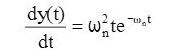
- 2. Impulse response of a second-order system:
The Laplace transform of a unit-impulse input is R(s) = 1.
The unit impulse response is give by:

Conclusion
In this tutorial we have discussed second order systems and their responses. As we are now done with the order of systems we will move on to Transient Response Analysis of Control Systems. Stay tuned for more insight on control systems.
Nasir.
2014/08/05 at 1:03 pm #13505AnonymousGuestRight here is the perfect site for everyone who hopes to find out about this topic.
You understand so much its almost hard to argue with
you (not that I personally will need to…HaHa). You definitely put a brand new spin on a topic which has been written about for
many years. Excellent stuff, just excellent!Review my website male enhancement testosterone pulmonary doctors in new
- AuthorPosts
- You must be logged in to reply to this topic.