Home › Electrical Engineering Forum › General Discussion › Inspection and Testing of Wiring Installations
- This topic has 4 replies, 3 voices, and was last updated 10 years, 3 months ago by
Anonymous.
-
AuthorPosts
-
2014/02/19 at 10:15 am #11137
admin
KeymasterHello everybody! As you may know, you can send us articles about whatever you want so that we can publish them on the blog. Manish, a member of the community took the opportunity and sent us the following article in which he tells us how to inspect and test your wiring installations. We thank him!
Just a reminder: you can send articles too by sending a mail to the team.
Introduction
Periodic inspection and testing of internal wiring installations is necessary. Internal wiring should be checked every year for safe operations.
While carrying out inspection and testing of internal wiring installations, following points should be checked:
Incoming Service Line Connection
Check and ensure the following:
- Service line coming in to the premises is properly terminated and brought in
- Check for fuse wire rating on each of the phases so as to ensure it is of correct rating
- Check for wire sizes to be of correct size to carry the required current
- Check for earthing to be properly maintained at the service line side
Main Switch Board
A main switch board exists at the point of termination of service line. Supply is provided through this board in to the premises.
- Ensure that the main switch board is closer to the point of supply in the premises
- Check for fuses / circuit breakers used of adequate sizes for all phases
- Check for correct ON/OFF working of Main Switch. A main switch plays a very important role as it helps to switch off the complete supply of the premises in case of emergency / repairs. It should always be in good working condition.
Check for any mechanical faults in switching operations that might cause it to remain continuously in ON state. This may be problematic in emergency cases when the electrician wants to switch the supply off - Ensure that the Switch board assembly is well covered to protect against rain / weather conditions
- Inspect to see that you are clearly able to trace the neutral and earthing wires in different colour
- Inspect the electricity meter connections are properly fastened
Internal Wiring Circuits
Internal Wiring Circuits are to be checked for following points:
- Ensure that each circuit branching out of Main Switch board has a connected load of not more than 800 watts or 10 points
- Test for Insulation resistance of conductor and earth to be as per IEC specifications
- Electrical resistance from connection with Earth electrode should not be more than one ohm
- Ensure metallic covering of iron clad switches, distribution boards are properly earther
- Test that that leakage current is less than 1/5,000 of maximum supply current.
Key Tests to be performed for Wiring Installations
- Insulation Resistance Test:
In this test, the insulation resistance of a wire is tested to ensure that there is no leakage current flowing through it. As per IE rules, the insulation resistance between wiring and earth should not exceed 1/5,000 of the current flowing through it.
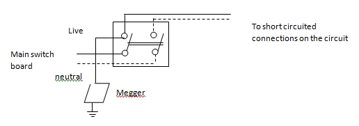
The test is performed using “Megger” instrument. In this, main switch is put in OFF condition and all the lighting connections on the circuit are short circuited. The Megger is connected between line and the earth. Megger is then rotated to generate voltage and then the reading on the dial of Megger is noted.
(See fig. below)
The insulation resistance should not be less than 50 Mega-ohm divided by no. of circuits. The insulation resistance per circuit is calculated as 50 M. If the result value is more than 1 then it should be considered as 1 mega-ohm. In no case this value should be less than 0.5 mega ohm.
- Earth Continuity Test:
This is second most important test for safety of installation.All metal clad switches, metal parts, covers, conduits must be solidly connected to earth. In absence of this, there could be a severe damage to the whole electrical installation, appliances connected to it. In adverse events, the leakage current flowing through it may cause severe electrical shock to the person coming in physical contact with it.
In order to test this, the main switch should be in open position. All other circuit contacts like bulbs and switches should be ON position. The Earth continuity tester is then connected between the switch / conduit and an independent earth. The tester will indicate the value of resistance. In all cases the value should not exceed more than 1 ohm. If the value appears higher than 1 ohm it indicates that the switch / conduit is not properly earthed.
2014/02/22 at 5:07 pm #13414adel deghady
Participantgood subject
2014/02/27 at 6:38 pm #13418Anonymous
GuestI`m a student taking bachelor of engineering in electrical engineering here in Tanzania,I`ve much intellested with the blog cause i`ll learn much from you concerning eletrical engineering
2014/08/09 at 5:17 pm #13511Anonymous
GuestWonderful goods from you, man. I have be aware your stuff prior to and you are just extremely fantastic.
I really like what you’ve obtained right here, really like what you’re saying and the best way
by which you assert it. You’re making it entertaining and you still take
care of to stay it sensible. I cant wait to read far more from you.
That is actually a tremendous web site.For a wonderful informative review please visit this post
– deva (http://clan.gentlemen-soldiers.net/index.php?mod=users&action=view&id=14775)2014/09/04 at 5:00 pm #13551Anonymous
GuestI think the admin of this website is in fact working hard in support of his website, because here every stuff is quality based data.
Here is my blog Inlyte cnet reviews
-
AuthorPosts
- You must be logged in to reply to this topic.
