Home › Electrical Engineering Forum › General Discussion › How to calculate the load? (back to basics)
- This topic has 1 reply, 2 voices, and was last updated 11 years, 4 months ago by
 Sajawal.
- AuthorPosts
- 2014/12/23 at 10:23 am #11222
 adminKeymaster
New back to basics article from one of our kind member of the community. What do you think about it?
One of the important things in the design of an electrical installation either on middle or low voltage is to choose the right conductor for the given consumers. Therefore, in this article I will examine how to calculate the load and what type of conductor you can use in the different situations.To figure out the load we need to calculate the current that flows through the conductor. We can calculate it very easily via the well-known formula:
P=U*I*cosϕ, where:
P – power
U – voltage of the network
I – current
cosϕ – power factor
Let us assume that cosϕ=1, in that way the formula will become P=U*I, and from here we can deduce the formula for the current
For single-phase electrical installations on low voltage the formula is:
For example if we have consumer with power 1,45кW and 240V the current that will flow will be:

There is also an easier way to calculate the amps and it is when you make a constant. For 240V the constant will be 1000W/240V=4,17.Once you have that constant, just multiply the power of the consumer by this constant and you will get the amps.
I=1,45*4,17=6,05A
For three-phase electrical installations on low and middle voltage the formula is:

with the same power 1,45kW and 400V the current will be:
Here the constant that you have to multiply is: 1000/(400*√3)=1,45.
Or the formula for the current flow will be: I=1,45*1,45=2,1A
This is the way by which the loads have to be calculated in an electrical installation and according to them you have to choose the right conductor. The conductors are mainly copper and aluminum. They also divide to a voltage level, protection level and the lying site conductors.
Different types of conductors for low voltage

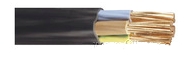
Power cable, Cu-conductor, PVC-insulation, PVC-sheathing for distribution and transmission of electric power at construction of distribution grids and installations with nominal voltage 1kV and frequency 50 Hz. Suitable for fixed outdoor laying or indoors, in cable ducts, tunnels, draw-in pits and ditches.
Power cable, Cu-conductor, PVC-insulation, armoured with steel tapes, PVC-sheathing for fixed laying in grids and installations, designed for transmission and distribution of electric power at nominal voltage 1kV and frequency 50 Hz.
Power cable, Al-conductor, PVC-insulation, PVC-sheathing for distribution and transmission of electric power at construction of distribution grids and installations with nominal voltage 1kV and frequency 50 Hz. Suitable for fixed outdoor laying or indoors, in cable ducts, tunnels, draw-in pits and ditches.
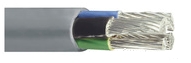
Flat installation conductor, Cu-wires, PVC-insulation, PVC-sheath for fixed installation in lighting networks and electric power installations.
Conductor with flexible Cu-wires, PVC insulation and sheath for connection of electrical appliances to the electrical grid, connection of mobile users, devices and appliances.Different types of conductors for middle voltage

Power cable, Cu-conductor, XLPE-insulation, PVC-sheath for fixed laying in grids and installations, designed for transmission and distribution of electric power at nominal voltages 6,10,20,30,35kV, and frequency 50 Hz. Suitable for fixed indoor installation, in cable ducts, tunnels and draw-in-pits, on cable trays and racks, directly underground and outdoors under shelters.
Power cable, Al-conductor, PVC-insulation, armoring, PVC-sheath for fixed installation in grids and installations, designed for transmission and distribution of electric power at nominal voltage 6kV and frequency 50 Hz.
Power cable, Cu-conductor with XLPE insulation and longitudinally water-tight conductive wrapping in the screen zone, for construction of urban and local supply networks, for connection of transformer substations in industrial facilities and projects. Designed for transmission and distribution of electric power at nominal voltages 6, 10,20,30kV.Besides these conductors there are many other types and this is why after you calculate the loads, before you buy the conductor, ask the consultants in the store which one is the best choice for you. The copper conductor is always better than the aluminum one because of its better properties but it is more expensive too.
When you are installing aluminum conductors beware for two things:
- Cut the conductor with a hand tool because if you cut it with a grinder for example, the conductor may smear and you will not be able to put a cable lug.
- Do not twist the conductor too much because it can break easily.
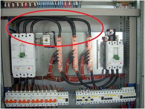
If the load is too big for one conductor, you can connect two conductors in parallel and thus the load will be distributed between them.

In a conclusion we can say that it is very important to calculate the load and to choose the right conductor for an electrical installation because if you install an inappropriate conductor may became a fire.
Pretty nice back to basics articles isn’t it? Give your impressions in the comments below.
2015/01/20 at 10:40 am #13643SajawalParticipantI want to know something a circuit it is a DB with switches what is confusing is how the load was calculated and what formulas are used.
All switches have Amp shows 10 A to 20 A on 240 Supply line ( LT line is 220 – 240 V )
Detail of switches
10 of 10A
5 of 20A ( For Air Conditioners )
3 of 15A ( for power sockets )
Total No. of switches 18
Total load is calculated and given is 18.80How did they calculate it.
BR
Sajawal
- AuthorPosts


- You must be logged in to reply to this topic.