Home › Electrical Engineering Forum › General Discussion › How does an Inverter Work?
- This topic has 3 replies, 2 voices, and was last updated 11 years, 3 months ago by
Anonymous.
-
AuthorPosts
-
2013/11/08 at 4:10 pm #11102
admin
KeymasterMore basic knowledge thanks to Nasir and his series of tutorials about inverters! This is part 2, leave your impressions.
Since the function of inverter is now clear, that it simply converts DC to AC, so next we come towards the working of an inverter, that how it performs this inversion process.
Inversion is the process of converting the DC to AC. To understand this process, first we would have to look on how an alternator produces AC.
Functioning of an Alternator
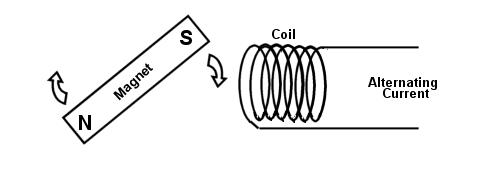
The figure shows a coil which is placed in front of a two pole magnet. When the magnet rotates in front of the coil, a current is induced inside the coil. When the north pole of the magnet comes near the coil, the current reaches its peak value in one direction.
As the North Pole moves further away, the value of the current also decreases gradually and when the south pole of the magnet comes near the coil, the current in the coil reaches its maximum value in the opposite direction. And hence this process goes on.
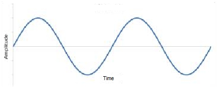
The output waveform of the current after this process comes as follows:
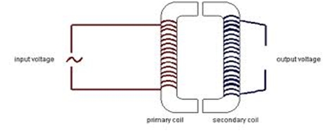
This is a sinusoidal waveform. The similar process occurs in a transformer as well, which can increase or decrease the amplitude of the alternating voltage.
The difference is just that instead of the magnet, there is a coil which is given a supply of AC as follows:
Producing AC through DC
Now the main question is that if we give a DC voltage instead of this AC as the primary input voltage, then how can we get an AC voltage at the output, as the inverter does?
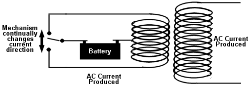
One method is to connect the switch as reverse the direction of its contacts after every half cycle of DC, so that the direction of output also changes after every half cycle and an AC wave can be obtained.
This process is shown in the following figure:
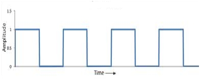
The output waveform of this process is:
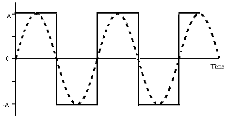
But this process of converting DC to AC was used in old inverters, which gave the output in the form of a square wave. A better result would be a pure AC sinusoidal wave as the output.
One solution for this thing is that we convert the output square wave into sinusoidal wave using some filtering system which would round off the square edges and hence transform the square wave into a sinusoidal wave.
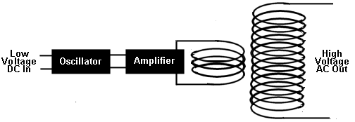
Another method is to give a half sinusoidal DC at the input so that we get a perfect sinusoidal AC at the output. For this purpose we would have to use an oscillator and transistors so that we can get the desired output. The oscillator would provide the necessary oscillations and then we could amplify the signals by using an amplifier and get the AC voltage through the transformer.
This process can be shown as follows:
Using these methods; we can get an inverter to convert DC power into AC. Although different types of inverters use different inversion methods; but the principle is more or less the same.
In our upcoming tutorials on these inverters, we will see these different types in details along with their applications and functioning. So keep visiting us and stay updated. More on inverters is on its way to enhance your knowledge!
Nasir.
2013/11/12 at 8:27 pm #13377Anonymous
GuestI am busy designing a project using PV solar panels to generate 3kWh of DC energy to charge up a battery via a regulator. Thereafter, connecting it to an inverter to produce AC power. What calculations do I perform to rate the inverter to produce the maximum output and also extend the life of the inverter? Thank you.
2013/11/25 at 11:54 am #13384admin
KeymasterHi Vivian,
Maximum output is usually taken in terms of the efficiency of inverter. Hence in order to increase the efficiency of inverter, the main thing to be considered is the pure sine wave generation. Usually inverters generate modified sine wave which causes the dissipation of energy. In order to increase the life of inverter use high quality components. Attach ink with component especially with the IC regulators and also add a small fan.
2013/11/27 at 9:00 pm #13387Anonymous
GuestSiemens have good guides about.
They belongs to the “quickSTEP Online Courses”“BASICS OF AC DRIVERS” is one of the related guides about this subject.
http://www.freeinfosociety.com/media/pdf/393.pdf -
AuthorPosts
- You must be logged in to reply to this topic.
