Home › Electrical Engineering Forum › General Discussion › Harmonic filter for better power quality
- This topic has 68 replies, 8 voices, and was last updated 8 years, 10 months ago by
 Anonymous.
-
AuthorPosts
-
2010/09/02 at 8:33 am #10216
 FrancoisParticipant
Power Quality Optimization with Active Harmonic Filter :
 It is widely believed that active harmonics filters (AHF) are very costly and, therefore, are the last choice for power quality solutions. The answer is it depends. Every harmonics mitigation and power factor correction device has its place in the market.
Knowing what a solution does for power quality and the advantages and disadvantages of each solution provide optimized solutions with maximum benefits for the user.
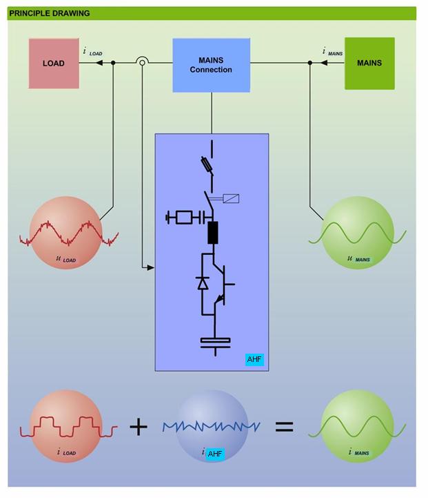
Active harmonics filters provide controlled current injection to remove harmonic current from the source side of electrical system s and reactive current to correct for poor displacement power factor (PF). Active harmonics filters can be applied to a single nonlinear load or many. The nonlinear loads can be mixed types or devices, such as variable frequency drives (VFD), DC motor speed controls (aka DC drives), uninterruptible power supplies (UPS), or thyristor (DC) power supplies, to name a few.
When is the best value achieved with active harmonic filters?
- When more than one nonlinear load and/or type of loads are present : DC drives, UPS, VFD, and others can operate on the same electrical system as an active harmonics filter system
- When input line reactors are used to reduce the total harmonics distortion of nonlinear loads.
- When 6-pulse rectifiers are employed in DC drives, UPS, VFD or DC power supplies.
- When thyristor rectifiers are used and power factor and harmonics correction are required : DC drives and DC power supplies require power factor correction and harmonic mitigation.
- When PF correction is required where high harmonics content is present : Poor power factor in an electrical system a high content of nonlinear loads cannot be performed by traditional power factor correction capacitor systems
- Where rapid in-rush or step load changes require support (aka VAR compensation) to stop flicker : The power quality of an electrical system is quite poor due to the massive voltage variations caused by the loads.
- When meeting harmonics specifications within your facility.
The nature of harmonic currents is that they are vector sums of the amplitudes, current and voltage, at each harmonic order. That is they are the root sum square of each harmonic order times the cosine of the phase angle differences between the vectors. Vector math makes 1+1 = Sqrt 2 (1.414) not 2. Active harmonic filter selection uses this to actually reduce the per amp size of the active filter as the quantity of nonlinear loads increases. Individual solutions (that is per rectifier) must be sized for the full amplitude harmonic spectrum making them, collectively, more expensive and physically larger than AHF
6-pulse rectifiers produce the highest level of harmonic current among three phase loads. If no impedance is present as an input line reactor or a DC bus choke (for diode rectifiers only), 6-p rectifiers may approach 100-120% total harmonic current distortion (TDD). A first step to reduce this very high level of TDD is to insert 3-5 % impedance line reactance to reduce the TDD to about 32-40% per rectifier. Then the AHF is selected for this much lower TDD level. Thus the AHF size is reduced due to the inexpensive insertion of inductors.
Thyristor rectifiers are known as phase controlled rectifiers. Thyristors are turned on at varying points in the AC waveform to control the power delivered to the DC side of the rectifier. This process causes displacement PF variations and harmonics. The interesting point is that maximum harmonics occur at best displacement PF and vice versa. The AHF is the best device to provide exactly what is required to achieve best total or true PF – highest lagging PF and lowest TDD – all the time. This achieves high levels of power quality.
It is always difficult to select tuned PF capacitor systems when the harmonics content is high. The tuning tends to be difficult due to the amplitude of harmonic current that flows through the capacitor circuit. The solution is to make the PF capacitor VARs larger so as not to over load the capacitors. This may preserve the capacitors but can cause leading PF at times. AHF will not cause leading PF at any time and don’t care if harmonics are present while performing PF correction.
Loads that cause flicker (light intensity variations due to rapid line voltage variations) are very short duration events – sometimes as short as 2-3 cycles. AHF are fast enough to provide support in about 100 microseconds. Often the AHF can be packaged with PF capacitor stages to create a hybrid VAR compensation (HVC) system for price and physical size optimization.
When applying harmonics standards inside a facility, the solution is sometimes difficult to attain. This is usually due to the low short circuit current capacity of the point of common coupling chosen within the plant. AHF make meeting or exceeding the standard simple, effective, and complete.
Does the above help you understand AHF and power quality?
What can we do to help you further?
Jim Johnson
2010/09/02 at 8:33 am #11405AnonymousGuestwill kvar effects generation & transmission
2010/09/02 at 8:33 am #11406AnonymousGuestUitlity systems have the ability to provide KW (voltage and current in phase), KVAR (voltage and current out of phase), and harmonic current (current at integer multiples of the base frequency). VAR and harmonic current are conducted in the power cables.
VAR current proportionally reduces the ability of the grid to provide real current (KW).
Harmonic current causes heating disproportionate to its amplitude. Heating effect is much larger than actual current amplitude.
When loads demand either VAR or harmonic current, the grid capacity is reduced. Therefore, the grid conductors must be oversized where this occurs. The solution to prevent over utilization or oversizing of the grid due to VAR and harmonic current is to provide the source of each locally and remove the demand from the grid – PF correction and harmonic filters.From the generation side, when rotating generators are used to produce the power, the generator has the ability to provide VAR support readily. It is the electrical nature of the generator. Generators do not like to produce harmonic current – extra heating occurs – but can.
However, as we move to more and more alternative methods of power generation, the electronics used to create the power (from PV or wind or etc.) only produce KW. Thus a need of alternate KVAR and harmonic support is required. This can be local by the user or universal by the utility. The cost must be born by the user in all cases.
From an energy efficiency stand point, local support for both KVAR and harmonic current reduces the cost of transmission (size of cables and alternate sources) and utilization of the grid. It permits more KW to be transmitted on the existing cables and permits planning of future grids to include smaller cables = less mineral resources consumed and processed. It helps make the planet greener.
2010/09/02 at 8:34 am #11407AnonymousGuestThis blog is fantastic by johnson and is too technical. I simply love it and I want to ask one thing to Jim, What is exactly the diff. between tuned and de-tuned harmonic filter. Which one is appropriate for VFDs? what is the exact process of connecting the filters with the load? Is there any good quality makes available in the market? Please confirm
2010/09/02 at 8:34 am #11408AnonymousGuestThanks for the compliment. The subject is not simple – it gets tough to make it simple.
A PF capacitor when placed in an electrical system has a resonant frequency based upon the inductance of the electrical system (from any point) and the capacitance of the PF capacitors. The PF capacitors are installed parallel to the loads. Adding a reactor in the parallel portion of the circuit in series with the capacitors modifies the frequency of the PF capacitor bank and thus the resonant frequency of the PF capacitor bank in the electrical system. This is ‘detuning.’
PF capacitors will interact with all frequencies present in the electrical system. When harmonics are present this is harmfull to the capacitors. The harmonic currents will overheat the PF capacitors to shorten its life or trip its thermal safety devices. Detuning can be designed to ‘block’ most of the harmonic currents or can be designed to permit the current of one harmonic frequency to flow into the capacitors. The ‘blocking’ design is considered ‘detuned’ within the industry. The design that permits a harmonic order to flow into the capacitors is called a ‘tuned’ capacitor or a harmonic filter.
Detuned and tuned capacitor systems are typically of two application philosophies. One is an electrical system solution where one large bank is used for a group of loads or used at the utility connection. Local and worldwide suppliers of these exist. However, a harmonic study is required for these types of solutions. Be sure the company chosen can provide this before equipment is purchased.
The second philosophy is to place a small tuned capacitor system at each nonlinear load to provide harmonic suppression for the electrical system. To be sure that these small tuned banks do not interact with each other (when more than one is installed) or overload due the presence of other sources of harmonics, a series reactor on the source side of the filter section is required. The series reactor is sized for the full load current of the nonlinear load on which applied.
The tuned filter also provides leading reactive current that must be evaluated within the system to determine if problems may occur due to excessive leading PF. The manufacturers of these type of filters tend to be localized operations within individual conutries. They exists in many countries.
The result of properly applying either device will relieve the utility of conducting VARs and specific harmonics and permit green generation technologies to be more easily employed.
Regards
2010/09/30 at 6:55 am #11435AnonymousGuestthe best thing about AC motors is that they require less maintanennance'”;
2010/10/17 at 6:13 pm #11554AnonymousGuestAC motors are really more efficient than DC motors, requires less maintennance too’,:
2010/11/05 at 2:05 pm #11602Alen MatanovicParticipantI'm not going to post new topic, because this one is perfect for my question,, as well as i hope the help will be ;)..
I'm expirencing some problems (that are more “theoretical” nature) with harmonic filters.. I can't seem to find how to properly calculate the values for inductance and capacitance of “notch” filter, actually, I just don't know the way to do it..
I need to desing notch harmonic filters for 5th and 7th harmonic (eventually for 11th and 13th as well).. Actually, I have allready made my dijagrame in EasyPower programe, and I'm supose to do harmonic analysis of it.. Here You can see some “print screens” of my project (it's pretty simple one) that consists of 4 loads, 1 linear and 3 nonlinear.. transformer is able to atenuate “triplens” but, because at my loads 5th, 7th, 11th and 13th harmonics are dominant,, I still have significant current THDi at PCC point of sistem..
First I want to apologize in advance for facts that load names and other stuff are not in English,, as well as for my English because I'm no native speaker..
So,, here are my pics:
one-line diagrame:

harmonic analysis mode (filters off):
and options I have to specify them:
Loads spectrums:
and current spectrum @ delta winding of transformer:
I can see mister Johnson is really “into” the subject, so I hope he will be able to provide some help or advice ;)..
Every help is warmly welcome ;)..
Thanks,, Alen..
2010/11/07 at 5:18 pm #11626AnonymousGuestfor years we have been using ac motors for industrial use and yes they last longer –
2010/11/22 at 7:23 am #11622AnonymousGuestI have read your comments on Harmonic Fillters. I am really impressed on your knowledge about power conditioning.We are facing one problem regarding harmonics. We have various ratings of induction motors at our water pumping stations in NASIK, INDIA. The motors are 440V ratings from 3HP to 300HP at almost all sites. At 2 sites, we have 3.3KV 430HP and 1000HP motors. We are using conventional DOL , Star delta and Auto transformer starters. The Electricity board has sent us notice that at some sites, near the metering point , the supply checked is distorted and THD found from 10 to 25%. We are not using any types of drives, we do not have UPS, Inverter, Rectifiers or any type of electronic switching devices. How can harmonics be created by our load? Is it possible? We are maintaining power factor unity at all our sites. Is it possible that at some point if power factor goes leading, harmonics are generated? Will leading power factor create harmonics? Is it possible that harmonics are entering from electricity board line? Please explain current / voltage harmonics.
2010/11/22 at 3:39 pm #11630AnonymousGuestHI, Umesh,
When there an no nonlinear loads present and PF capacitors (PFC) are used to raise the displacment PF (DPF) above about 0.95 lagging, the issue is usually resonance.
You indicated the DPF objective is unity. Attempting to maintain above about 0.95 lagging DPF with PFC is often dangerous and results in exactly what you have stated.
PFC are designed to switch slowly. The result is that at times the DPF goes leading. If curcumstances are correct resonance with the utility PFC can occur. One sympton is that the mains voltage rises before the resonance begins.
As a general rule, Schnieder Electric dos not recommend using PFC to correct for DPF above 0.95 lagging. We suggest using an active harmonic filter. Active harmonic filters (AHF) provide DPF correction by injecting phase shifted current electronically. This eliminates the possibility of resonance.
You can use PFC to correct to 0.95 lagging and supplement the rest to unity with AHF.
Please contact your Schneider Electric sales and aplication center in India for assistance.
Thanks for writing and good luck.
2010/11/22 at 4:12 pm #11631AnonymousGuestHi, Alen,
Sorry for the late response. I was answering another comment when I saw your question.
I’m not able to see the details of load sizes in your attachements. So, I will make general comments.
Using power factor capacitors (PFC) with detuning to make 5th and 7th harmonic filters is always questionable. The reason is the amount of leading VARs injected by the two filters. If often exceeds the required VAR injection and leading displacement PF occurs. Leading PF can cause the safety devices (circuit breakers and contactors) to fail over time. Also, if the leading level is high enough other customers or the utility may experience resonance. You will see elevated mains voltage levels.
Schneider Electric generally recommends the following regarding nonlinear load content:
a) If the nonlinear content of total load is less then 15%, then standard PF capacitors can be used.
b) If the nonliear content is between 15 and 50% of content, then detuned PF capacitor systems are used.
c) If the nonliear content exceeds 50% of content, then actice harmonic filters are used for PF correction.
It sounds like (based upon your brief description) that your nonlinear content is over 50% of the total load. If so you may need some displacment PF correction but not as much as paralleld 5th and 7th order filters will inject.
Active harmonic filters (AHF) inject controlled reactive current for displacement PF correction and harmonic mitigation. Current transformers are used to define the load current so AHF inject only what is required to attain the set point displacment PF and 5% TDD for harmonics. There is no chance of over correcting displacement PF and thus no chance of leading PF.
I suggest you contact your local Schneider Electric specialists for assistance.
Regrads, Jim
2010/11/22 at 4:42 pm #11632AnonymousGuestHello, Owen, Garage and Kerstein,
I don’t know where this discussion come from but I will offer some comments.
Direct on line (DOL) AC motors are the worldwide standard to produce mechanical work from electricity. No dispute. Its huge.
DOL AC motors provde fixed speed operation. They are dependable and last a long time if environmental conditions are maintained to standard.
DC motors are only used when variable speed is needed and a DC controller (DC drive) is required.
So any discussion about comparing DC and AC motors requires a discussion about the motor controllers also.
DC motors are more efficient than AC motors. Typically DC motors are 97-99% efficient. AC motors are not more than 94% efficient (check the manufacturers’ tables).
DC drives are 99% efficient. AC motor speed controls (PWM VFD) are at best 97-98% efficient. Typically about 97%.
But efficiency is only one part of the discussion. Maintainence is another issue. DC motors require maintenence for the brushes. AC motors need grease and they run forever.
DC drives are simple and less costly and easy to maintain. PWM VFD are more complex and do require more maintenece than DC drives.
DC motors are considered special and have relatively long deliveries. AC motors for DOL use are stocked and readily available. For a given size rating, the DC motor is larger physically.
AC motors to be used with PWM VFD require a different design than do standard DOL AC motors. NEMA and other bodies have defined how these differ. Needless to say the AC motor that operates on VFD should be special.
Trade offs abound.
Generally, PWM VFD with AC motors are used as a preference over DC dirve and motors – today.
Regards,
2010/11/22 at 11:43 pm #11633Alen MatanovicParticipantThank You for brief help..
In meanwhile I've found the way to calculate needed values for capacitor and inductor (needed by programe) and I've got some new “printsreens” to share:
impendance caracteristics @ bus – 3
and reduction of THDi to some 7% at PCC:
Still, I want to ask something more,, what does this voltage presents, and how to determin it's value,, and I mean on the Voltage that is required by Programme as You can see at my first post in fllter data picture? I've set aprox. voltage level of 430V (because main is 400V) just to perform calculation,, and it seemed to work, but I'm looking to find formula for it's precise calculation..
Also, I'm able to change my loads specifications because they are not strictly set,, so if I change from kVA@pf – to – kW and kVAr,, nothing changes, from my perspective of problem,, because if I just “add” those kVArs I'm not sure if I'm geting proper value for my capacitor bank.. Lets say, for example, if my linear load is set as: 100 kW and 20 kVAr, and orher three, ASD 40 kW and 5 kVAr, Fluo. lighting 25 kW and 5 kVAr,, and PC center 30 kW and 5 kVAr,, simple problem is how should I properly add those to gain value for reactive power request by my loads.. I asume that linear load would have “ohmic” character, ASD drive “inductive”,, and Fluo and PCs “capacitive” character,, so simple adding (20+5+5+5=35 kVAr) is definatelly questionable,, more proper way would be “phazor” addition.. but interesting fact is that if I set my filters capacitor bank to 0.035 MVAr it provides better THDi atteunation than it's if I set it to phazor value 20,616 kVAr,, I supose that programe is not able to differ those differences.. Once knowing this “voltage” and “capacitance” it's simple to calculate “inductance” using Thompsons relation..
So I'm still “stuck” browsing around for more details about this “voltage”..
The only information provided by programmes “manual” and “help” is:
Filter Data:
• Resistor: Resistance of resistor of the filter in ohms.
• Inductor: Real and imaginary impedances (ohmic resistance and inductive reactance) at system frequency in ohms.
• Capacitor Bank (1 and 2): The reactive power of capacitors for the system frequency in MVARs at the voltage level specified in kilovolts
… which doesn't helps me very much..
Here are also the links for my calculation of those filters, as well as “reverse” calculation (that's the way I found to calculate my filters) of filters that are provided in example in the users guide of this book (I'm going to apologize again, now for two reasons, first is those materials are not in English, since I'm from adriatic region, but You can see/look only at calculations…. other reason for apologize is “messy” pdfs because my scanner just got broken, so I was using my camera)..
“primjer iz knjige” would be “example from the book” and “računanje filtera” would be my filter calculation..
example form the book (please notice that “2.filter” and “3.filter” are notch 5th and 7th filters respectively….. how come is Xc value different for both filters and it's close to 20 MVAr set by the load?……. there You can also see those voltages like 120 kV that are set “in decimal”):
[Link removed by moderator team]
calculation (please look on the page 3. for calculation of my filters,, and on page 2. for reverse calculation of filters from book example):
[Link removed by moderator team]
Kind Regards,, Alen..
(P.S. Please note that links to illegal downloads will be removed from this forum. – Moderator Team)
2010/11/23 at 9:31 am #11635Alen MatanovicParticipantCould this voltage be something that is mentioned in following Schneider pdf,, page 22.??
http://www.electrical-installation.org/w/images/7/73/EIG_chap_L-2010_haute_def.pdf
(somewhere like in the middle of the page, related to 7-8% increase of fundamental 400V)
Thanks again,, and sorry for multiply posting ;)..
Regards,, Alen..
-
AuthorPosts


- You must be logged in to reply to this topic.