Home › Electrical Engineering Forum › General Discussion › Ground and test devices for engineers and technicians
- This topic has 1 reply, 2 voices, and was last updated 11 years, 9 months ago by
 Lesole.
- AuthorPosts
- 2014/08/18 at 11:39 am #11186
 adminKeymaster
Marvin M. from the community had the great idea to give advices regarding grounding and test devices. Enjoy and don’t forget to post your own advices if you have few.
Introduction
A ground and test device primarily applies personal protective grounds to the MV components and conductors in the assemblies. It is a primary necessity as it creates a safe working condition for the engineers and technicians.
In essence, it offers prime protection for the personnel, equipment and facilities. According to the set standards, achieving a prime electrically safe environment encompasses the following:
- Identify all energy sources in the working environment
- Isolate the sources
- Verify electrical source isolation
- Lockout the devices to the sources
- Test for voltage absence using the appropriate test device
- Apply temporary personal protective grounds
The above steps must be fulfilled before the actual grounding. Do note that negligence of any of the steps leads to disruption of the production process and injury to personnel. Luckily, for engineers and technicians, various standards have been set up governing ground and test devices.
[caption id="attachment_8279" align="aligncenter" width="510"]
 Fig.1 Ground and test device working principle[/caption]
The standard divides the test devices into two categories:
Manual Ground and Test Devices
These are the test devices with upper and lower terminals. An added connection connects the conductors to ground. Other than upper and lower terminals, manual test devices allow connecting either of the two terminals to test terminals. These test terminals can then connected the phase conductors to ground.
A manual switch connects either of the terminals to a set of other terminals. Manual ground and test devices do not have interrupters or a mechanism to interrupt or close an energized system. They only provide a solid grounding of the equipment during initial installation or routine maintenance, thereby safeguarding the personnel.
Electrical Ground and Test Devices
The major components of an electrical ground and testing systems include a grounding switch, test receptacles, selector switch and the operating mechanism. The unit frame contains the main operating mechanism, with the two switches and receptacles forming three similar poles assemblies.
An integrated electrical switch allows connection of either of the terminals to ground. Most of the modern, simple electrical devices have integrated test ports for voltage testing of the two terminals. This allows the device to apply the ground even when the whole system is energized.
Complex electrical ground and test devices, however, have an included manually operated switch that allows for connection to an electrical grounding switch. Additional components include an integrated electrical operator that closes the vacuum interrupter contacts. The electrical test devices are suitable for use for up to 50kA ratings. Some have the capability to handle up to 63 kVA.
Note that, even though the electrical ground and testing devices lack an interrupting mechanism, they have an integrated closing mechanism to protect against short circuit currents equivalent to the switchgear equipment rating.
The major purpose of the ground and test devices is to provide inter-terminal and phase barriers to prevent bridging between the live conductors, the ground and in between the terminals. This property is most important for the manual devices, as an engineer or technician utilizes cables and conductors to make the ground connection. For this purpose, insulating tools such as hot sticks are applied to prevent injury.
Before applying the devices, especially manual devices, it is important to de-energize the system. Do note that the manual devices lack provision to establish ground if the system is energized. In addition, ensure that there is clear co-ordination between the manual device and the switchgear. This ensures that it meets the current withstand ratings to prevent injury and equipment damage.
Conclusion
The ground and test devices are necessities when chances of making an error are greatest, especially during initial installation, troubleshooting and routine maintenance.
Though there is integrated safety mechanism such as the closing mechanism in case of short circuit, the sole responsibility lies on the operator. They should be able to recognize the potential hazards and take due precautions.
Marvin M.
2014/09/16 at 6:48 pm #13574LesoleParticipanti need a sample on how to write a report on earth electrode and soil resistivity test. pliz help your brother.
- AuthorPosts
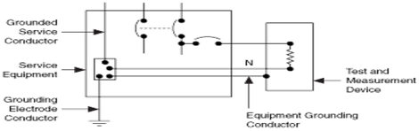 Fig.1 Ground and test device working principle[/caption]
- You must be logged in to reply to this topic.