Home › Electrical Engineering Forum › General Discussion › Current and Voltage sensors
- This topic has 1 reply, 2 voices, and was last updated 11 years, 3 months ago by
 dutuc_nicolae.
- AuthorPosts
- 2015/02/10 at 10:36 am #11230
 adminKeymaster
Here’s an article by our dear member Martin M. focusing on current and voltage sensors in terms of features, applications, and benefits. Enjoy and leave your impressions.
Introduction
Majority of faults, incidents, and accidents associated with electrical equipment and systems are as a result of undervoltage and overvoltage. It is important to know the exact amount of current and voltage is a particular system and application as it enables the engineer or technician to make and implement safety-critical decisions.
In addition, knowing the amount of current or voltage in a system allows one to gauge the performance of the various subcomponents in a system.
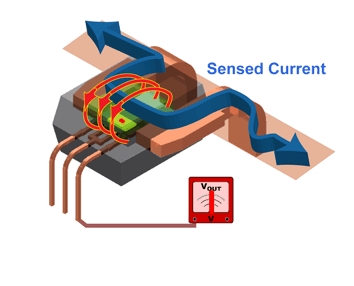
Current Sensors
There are two primary types of current sensors, direct and indirect sensors. The direct sensor applies Ohms Law and Halls Effect. It has an integrated coil. By placing the coil around a current-carrying conductor, there in an induced voltage, which is proportional to the current in the system. By using various amplifiers such as shunt and operational amplifiers, as well as a user-friendly interface, it is then easy to detect and measure the current in the system.
Do note that the shunt is designed to withstand short-circuit currents without any distortion to the resistance value. This allows an external, non-invasive way to measure the current. Direct sensors are used for low currents (<100A). For higher currents (100-1000A), the indirect method is used. It works on Ampere’s and Faraday’s Laws by measuring the magnetic field that surrounds a current carrying conductor.

Traditionally, current sensors were used for circuit protection and control. However, the values are presently used to monitor and enhance performance of different electronics and electrical equipment.
The various applications include the following:
- Linear and switch-mode power supplies monitoring
- Motor control
- Overload protection
- Over current protection
- Ground fault detection, amongst others
Voltage Sensors
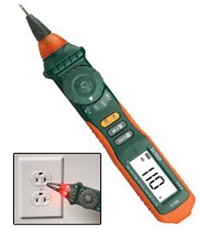
The primary function of voltage sensors is to detect and measure AC and/or DC voltage levels. When the presence of voltage is detected, the sensors provide an output in the form of analogue voltage signals, current levels, frequency and modulated frequency outputs or audible sounds.
A typical sensor features a needle or pointer, while the digital versions feature an alphanumeric interface. The sensors in use include handheld voltage sensors, DIN rail mounted sensors, and PCB mounted voltage sensors.

The voltage sensor is able to measure the presence of a voltage without making metal contact i.e. on insulated wires. A voltage sensor consists of a resistive voltage divider. The integrated resistors, embedded in a casted resin (for voltages between 1-72kV), have a low value inductance. The arrangement, mostly in a zigzag arrangement, together with the resin permittivity, results to a capacitance. This capacitance is more than any capacitance straying to the ground.Electric principles dictate that the smaller the capacitor, the larger the voltage. Thus, when you hold the voltage sensor in your hands, and place the tip near a live conductor, you create high impedance on the tip, thus forming a capacively-coupled series circuit. The circuit is complete through you, the ground, and back to the circuit. Thus, the voltage detector sensor tip is a small capacitor that is capacively-coupled to a live voltage.
There are various applications associated with voltage sensors. The common areas of use include power demand control areas, power failure detection, safety switching, revenue metering, load control especially in motors, power quality monitoring especially near VAR compensators and energy management control systems.
Others include:
- Power measurement: this is usually done on industrial equipment to measure efficiency
- DC voltage measurement
- Power quality measurement
- Earth fault measurement
- Switchgear optimization
Thanks for reading,
Martin M.
2015/02/11 at 2:20 pm #13649dutuc_nicolaeParticipantGreen power meter – live data monitor:
http://www.instructables.com/id/Green-power-live-data/ - AuthorPosts
- You must be logged in to reply to this topic.