Home › Electrical Engineering Forum › General Discussion › Auto Transformer
- This topic has 1 reply, 2 voices, and was last updated 10 years, 4 months ago by
Anonymous.
-
AuthorPosts
-
2013/07/19 at 3:22 pm #11051
admin
KeymasterNasir, a member of the Electical Engineers Community sent us a 11 parts tutorial on transformers. Today here’s the 9th part focused on Auto transformers. As for the previous parts, you can find them in the blog and on the forum.
An auto transformer is the one which consists of a single winding, part of which acts as the primary winding of the transformer, and some part of which acts the secondary winding, which can be varied by switching between the contacts of the transformer. By varying the contact of the switch we can change the number of turns which are accommodated in the secondary winding.
Since the output voltage depends upon the number of turns of the secondary winding, so in this way the voltage output can also be varied. For this reason, an auto transformer is also known as a “Variac” because it is mostly used to vary (step up or step down ) the output voltage which has to be supplied to the circuit.
Construction and working of an Auto Transformer
In general transformers, there are two windings which are magnetically linked to each other, but re physically separated from each other. But in an auto transformer, both the primary and secondary windings are connected to each other, both physically and magnetically.
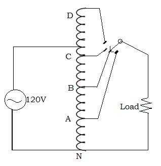
The internal construction of an auto transformer is shown in the figure below:
Here it can be seen that there is only a single winding, on which a number of points have been marked, and each point has equal number of turns, i.e. 40 turns between two consecutive points on the winding, which means 40 volts between those two points.
The primary voltage which is of 120 volts in this case, is supplied between the points C and N, as these points accommodate 120 turns as well. So the winding between point C and N is regarded as the Primary Winding over here.
Now the secondary winding will be the one, across which we connect the external load. Since auto transformers have a varying output voltage, so we connect a switch with the load, so that the contacts can be varied to step up or step down the secondary voltage. So as shown in the figure, we make one end of the load as a fixed end and connect it to the point N.
The other end of the load is connected on the switch, and the point to which the switch will be connected; will be the other point of the secondary winding. For example, in this figure, the secondary winding is between B and N.
In the transformer in the figure, a switch is used to switch between the points A, B, C and D. But if this switch is replaced by a sliding Tap, then the voltage could be varied continuously and this transformer could also be known as a “Variac”.
Applications of an Auto Transformer
As explained by the figure, an auto transformer has the capability to supply a varying secondary voltage to the externally connected load. So this is mostly used in applications where a continuously varying voltage output is required.
Some of its applications are listed below:
- It is used in electronics testing centers where continuously varying voltage supplies are required.
- In amplifiers or boosters, where high voltages are required.
- In other audio devices like speakers, these transformers are used for matching the impedance and adapting the device to a continuous voltage supply.
- At places like power stations which initially need to step down the voltage, then increase it to match the voltage required by the device at the receiving end.
Advantages of Auto Transformers
- Since only one winding is requires, so these transformers are cost efficient and relatively smaller.
- These are more efficient and require lower excitation currents than the conventional transformers.
- The varying of voltage is more easy and smooth in auto transformers, as compared to the conventional step up and step down transformers.
In the coming post, we will discuss the current transformer. Current transformer is used to measure current drawn by the load. It has a lot of applications in industries and we will discuss them all in the coming post. Thanks for reading!
Nasir.
2014/09/20 at 3:54 am #13582Anonymous
Guestcontinuously i used to read smaller posts which as well clear their motive, and that is also
happening with this paragraph which I am reading now.My webpage: verona plumbing supply
-
AuthorPosts
- You must be logged in to reply to this topic.
