Home › Electrical Engineering Forum › General Discussion › 3 Phase Transformers
- This topic has 2 replies, 2 voices, and was last updated 9 years, 7 months ago by
Anonymous.
-
AuthorPosts
-
2013/08/06 at 3:58 pm #11060
admin
KeymasterHere’s the last part of Nasir’s complete tutorial on Transformers (11 parts!). We’d like to thank him for his work and contribution. We are also open to suggestions if you need articles on any specific topic, let us know and we will try our best to post it.
Remember you can share your work, tutorials, debates, experience with us by sending a mail to the team.
Introduction
Voltage transformers can also be used to supply power to three or higher phase connections, in addition to single phase connections. Such transformers which can supply voltage to three or more phases are also known as Poly Phase transformers.
These transformers can be used to generate or supply power on large scales like for industrial or commercial uses. These have many advantages over single phase transformers as a three phase transformer provides a more economical approach by using less material since the three cores can be replaced by a single core.
Moreover the constant power transferring property of a balanced load improves the vibrations and fluctuations.
The three phases carry equal current which tends to cancel each other, due to this reason the neutral wire can be shortened and all the three phase wires are of equal length creating a balanced load system.
Construction of a three phase transformer
A three phase transformer can be constructed by connecting three single phase transformers with each other in such a way that the three primary windings of all the transformers are connected to each other and the other three secondary windings of them are also inter connected to each other. Then all the three phases will differ with each other with a phase angle of 120°.
Other than this way, a three phase transformer can also be constructed on a single core such that all the three windings are wound on that core instead of on three individual cores. This construction is more preferable as it is less costly and more convenient as core material is also saved.
The three windings of a three phase transformer are usually connected in two types of configurations:
- Wye connection
- Delta Connection
Wye Connection of Windings
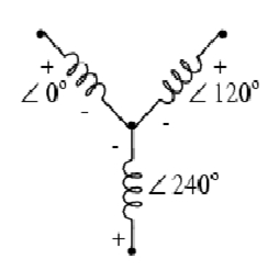
When one end of all the windings are connected with each other so that all the three ends form a common end point, then this type of connection is known as a Y or star connection.
The advantage of using wye connections is that multiple voltages can be achieved by using a wye connection.
A wye connection is shown in the figure below:
Delta Connection of Windings
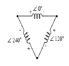
If all the windings are connected to each other end to end, such that one end of first winding is connected to the other end of the second winding and in this way all the three windings form a closed loop triangle, then this type of connection is known as delta connection of windings.
Delta connections are more safe and reliable for use since in case of failure of any one phase, the other two still tend to supply the full line voltage to the output.
Delta connection is shown in the figure below:
Now the primary and secondary windings can be connected in several different configurations which are as follow:
- Primary winding in Y and Secondary winding in Y
- Primary winding in Y and Secondary winding in delta
- Primary winding in delta and Secondary winding in delta
- Primary winding in delta and Secondary winding in wye
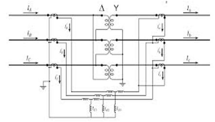
In general the three phase connections of a transformer can be made as follows:
The thing that should be noted here that the wye and delta connections of the windings are inter convertible and can be changed into equivalent forms of one another.
For example, for finding the equivalent voltage of a wye connection in delta connection, the following formula can be used:
Where, n is the turn ratio of the transformer.
And for current;
Similarly to convert delta into Y:
And for current;
This was the last post in the series of transformers. I have tried my best to explain everything in full detail. If you guys have any problem in any part of this tutorial, let me know and I will explain it in detail to you. Have fun. Take care.
Nasir.
2013/08/29 at 10:16 am #13357Anonymous
GuestIs possible to conect both neutral points of 2 three fase transformers to the same earthing connection?
What happens with the voltage in the LV part, when a three fase transformer lost de voltage in one fase of the HV part?
2015/07/07 at 10:27 am #13697Anonymous
Guestwhat is the energy efficiency, when only 2 primary wires feed a 240v delta, 4 wire system? it has 3 transformers feeding the load side of the demand.
-
AuthorPosts
- You must be logged in to reply to this topic.


