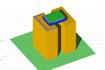
A good design of the PV system must be able to cover the needs of the customer and face the constraints, finding a technical and economic solution to the problem. Read Carlos’s solar design experience in Venezuela and share your story too in the comments.
Solar system design: the scope
Maybe one of the most challenging designs I’ve done had to do with a grid-tied with battery backup system that I had to design for a commercial business in Venezuela.
The business was aiming to cover the whole area available for solar panels on the roof and on the level of PH in order to back up loads in illumination, outlets, and servers of a complete floor of the building.
The purpose for these desires was related to the low reliability of the power grid in Venezuela, but also because the company wanted to promote itself as a green energy company and as one of the few in Venezuela that supported commercial PV systems.
Solar system design: space limits
The first constraint that I had to face was space. The building was still under construction and the plans of the architect were to install aluminum louvers that would cover the view of air conditioning machines, air vents, and ducts of solid wastes. That left me with a small hallway on every side of the building of nearly 1m in wide.
As you may know, to make proper use of the available space and to size the system to cover the needs of the client, I needed more space. Most solar panels over 200 Wp have at least 1m in wide and tend to change in length instead. But, solar panels get hotter underperformance and if there is no good ventilation then temperature losses are greater and could maybe even damage the panels.
Here in Venezuela, there is no normative regarding security measures or available space between panels, however, for maintenance, security and even for the installation itself, it is necessary to have a free corridor.
Discussing with the architects and the engineers of the construction was a tough work to convince them that it had to be done and that it could be done. Eventually, we found the solution to the problem and I was able to obtain 50 cm extra in wide, better than nothing right?
Solar system design restrictions
The second problem that arose was that due to the space constraints, the corridors for solar panels were all placed in different orientations facing South, North, East, and West. There is a typical idea related mainly to mismatch losses where multiple configurations could not be set in the same photovoltaic system going directly to the same MPPT input.
But, there was also another constraint, it had to be a three-phase system because the connection to the panelboard had three-phases and since the size of the system was big enough as to cause unbalance on the system, then the photovoltaic system had to be designed as a three-phase system.
Sizing a three-phase system using each string to avoid mismatch issues was non-sense, the costs and the space for equipment were just ridiculous. Therefore, my first idea related to use a hybrid inverter for this installation was not possible, because it would need to arrange all the strings with different orientations to the same MPPT input, which could lead to high levels of mismatch losses.
Therefore, I chose a DC coupled configuration with charge controllers in the design. Finding the charge controllers and an inverter/charger that could be coupled together with the existing electrical installation was another challenge.
For some reason, most inverters/chargers that work in the three-phase configuration have their power outputs in 400 V (phase-phase) or 230 V (line-neutral), and there are many others that only work under split-phase configuration 120V/240V. The low voltage of the grid in Venezuela is 120V/208V or 277V/480V, therefore, the only answer was to use an autotransformer to connect the system to the existing electrical installation.
When discussing this with the client, the client refused to add another equipment to the installation due to costs and space for equipment. Therefore, I had to keep looking for a solution.
Solar Designs with Multiple Orientations: the Answer
Eventually, I found a system that was DC coupled integrated with charge controllers, battery-based inverter with 48 V output for batteries (my case of design) and output in 120 V, the system was from the brand Outback Power and was called Three Phase Triple System.
The system was composed of three single-phase inverters that when synchronized between them by using a special device, they could be set in the three-phase configuration. Four charge controllers were needed to size them properly according to the power of the PV array and since there were four orientations then it was a perfect match since each orientation would go directly to each charge controller for an independent track of MPPT.
That way, the system fulfilled all the requirements, voltage coupling to the existing grid, power size, voltage for batteries, MPPT ranging, different orientation sizing and three-phase configuration.
Thank you for reading this career story by Carlos.
Do not hesitate to leave your questions and impressions to him in the comments section below.
