 New guest article today by A.N. abotu motor starting systems. If any remarks or questions are welcomed, write a comment below.
The asynchronous motors are used for a wide range of applications. They are used in industrial processes, commercial buildings, recreational areas, at home, and other areas.
However, if motor is switched on directly from the mains supply, it draws a very high initial current. The current at startup is usually between five and seven times what the motor normally draws at full load, but only develops a torque of between 1.5 and 2.5 times the torque at full load.
The large startup current leads to a huge voltage drops in the supply line, and this may cause instabilities in the line and affect the equipment connected in the same circuit.
As such, starting motors directly is not recommended and instead, it is advisable to use a suitable starting circuit or method that minimizes the initial current. This can be achieved by starting the motor at a lower voltage than normal and then increasing the voltage once the motor has started and gained adequate speed.
Motor starting methods
Using a Direct-on-line starter
The direct on line (DOL) starter combines startup and motor protection; it consists of a contactor and a protection device such as a circuit breaker.
The starter circuit has a coil operated contactor. This coil can be controlled by pressing either the start or the stop push buttons depending on the required operation. Pressing the start button energizes the contact, causing it to close the three phases and feed the motor with power.
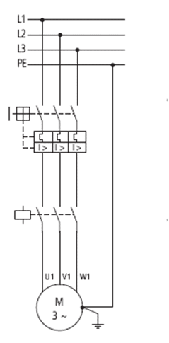
Direct-on-line DOL starter | image: moeller.es
Pressing the stop button will de-energize the contactor, disconnecting the supply to the motor and causing it to stop. However, it suffers from large inrush currents drawn when the full mains supply voltage is applied to the motor.
The DOL starters are limited to motors of less than 10 KW. Larger motors would cause excessive voltage drops due to the large startup current. In addition, the DOL subjects the motor to excessive heat, hence decreasing its lifespan.
Auto transformer starting
The method utilizes an autotransformer and a two position switch which is operated manually or automatically through a timer. Either operation changes over the switch position from the start position to the run position.
When the switch is at the start position, a fraction of the mains supply voltage is tapped from the auto-transformer. The autotransformer supply between 50 and 70 percent normal voltage value to the motor.
With a reduced startup voltage, the motor draws less current. For example, at a 50 % tap on the auto-transformer, the motor draws half its rated current or about 25% what the motor would draw with the DOL starter.
The autotransformer starter method is bulky and expensive and usually employed for larger industrial applications.
Star-Delta Starter
The motor employs both the star and delta configurations controlled by a changeover switch. The motor starts in the start configuration after which it is switched to run on delta configuration.
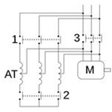
Star-delta motor starter configuration | image: bhs4.com
The motor is started with its rotor windings connected in a star configuration. The motor consumes a reduced current than the delta configuration – usually a third that of the delta. However, the star connection only develops half the torque compared to that of the delta connected.
The star-delta starter method uses a two-position automatic or manual switch, and a timing relay. This enables starting the motor in the star configuration which has a low start-up current, and then switching to the delta configuration after the motor has attained the required speed.
The method is more complex than the DOL and may not provide enough torque for the full load at startup; as such, it is usually used to start motors with an initial light load.
Rotor Resistance Starter
The method uses external resistors, initially connected in series with the rotor winding for each phase. The resistors, which are usually the wire wound type, drops some amount of voltage while limiting the current flowing into the rotor winding. Once the motor starts, the resistors are gradually removed from the circuit and power connected directly to the mains supply.
Electronically controlled motor starting
Soft start
Soft start, the method uses active switching devices such as thyristors to control the way the power is supplied to the motor. In three-phase motors, the method is applicable in both the in-line and in-delta configuration modes.
The method provides a means of controlling the motor voltage and the start-up current, hence enabling a smooth, surge-free increase in the motor torque. This reduces the voltage dips, the stress, and wear and tear on the mechanical parts.
Frequency Inverter
This is an electronically controlled method that allows smooth starting of asynchronous motors. It uses electronics inverter circuits to manage the frequency and current for the motor supply, hence preventing high startup currents. The smooth start-up prevents abrupt of the system’s mechanical parts. This is the best method, but also the most expensive.
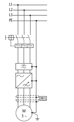
Frequency inverter motor starting | image: moeller.es
The acquisition and installation costs are higher due to the additional requirements, such as RFI filters, EMC, shielded motor cables, compatibility issues, etc.
However, there are more economical advantages when in operation. This includes a soft start, energy efficiency, reduced tear and wear of the mechanical parts, process optimization, etc. Other advantages include speed stability during load variations and an overall longer life of the motor.
Common motor starting methods comparison
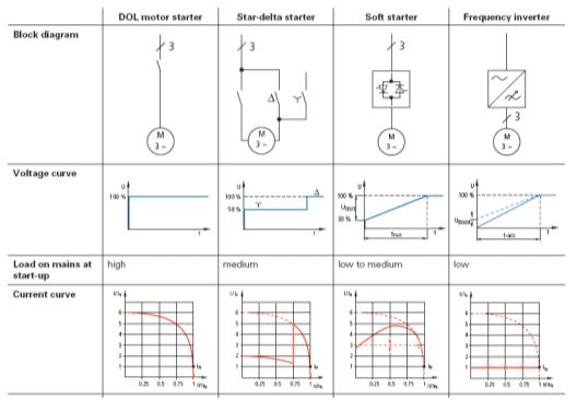
Comparison of some of the common motor starting methods | image: moeller.es
Conclusion
Due to their construction of asynchronous motors, the windings appear as a short circuit during start-up and the motor may draw a lot of current from the mains, accompanied by large voltage drops. This may result to instabilities and affect other equipment supplied from the same line.
There are different methods that can be used to start the motors at lower currents and then increased the supply to the normal value once the motor has started. The choice of the method is influenced by the size and application of the motor.
A.N
What’s your opinion about this back to basics article? Please post a comment in the area below.