
In most of the cases, the batteries have some inductive character, besides capacitive, and because of that fact they act as higher harmonics filter.
But in today’s article the case is different. Read Mile’s nice explanations below and don’t forget to comment afterwards…
In this case, we have only one system of batteries, and we make tests and analysis of the voltages and currents during switching of the equipment. We are making these tests, so we can determine the correct specs of the needed equipment that has to be installed, and to determine the parameters of the protective equipment.
Appearance of capacitors in the network causes some specific working regimes. The most important regime is the current at the start of the capacitor. This current can achieve greater value of more than 10 times of the nominal value.
Transient process in electric arc furnace
Our system consists of two transformers (the first one is 120 MVA with 110/30 kV and is called stepdown, while the other one is 100 MVA with 30/1000 kV and is called furnace), and capacitor batteries which are connected on 30 kV voltage level, as described on picture 1.
The power factor of the system is 0,7. In the system there are batteries with 40 MVAr installed power. The batteries are in two groups and combined with inductive components, so they can actually serve as harmonic filters.
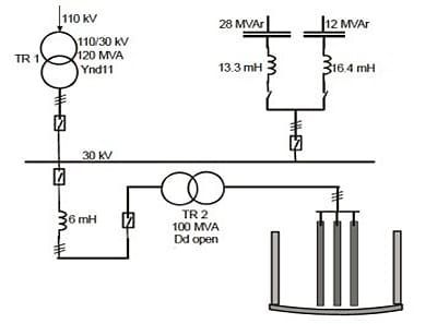
Picture 1. Electric arc furnace system
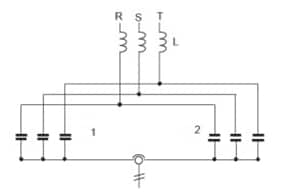
Picture 2. Battery group
Batteries are connected in two groups accompanied by inductive components, so we can compensate the enormous reactive power and filter the third and fourth harmonic.
For the third harmonic, in connection 1 we have 3 capacitor systems in series and 5 in parallel. For connection 2, we have 3 in series and 6 in parallel. For the fourth harmonic, we have 3 in series and 2 in parallel, while for connection 2 we have 3 in series and 3 in parallel.

Picture 3. Single phase diagram of the system
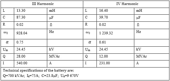
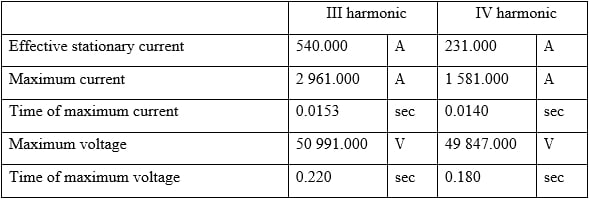
Table 1. Calculated values of the parameters
Current measurements
In the following section we will present the currents in the system during turning on the system.
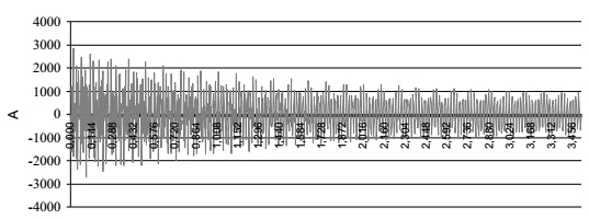
Picture 4. Current flow of the third harmonic
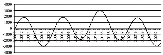
Picture 5. Current flow for the third harmonic for the first 25ms
In order to determine the maximum peak of the current, we need to analyze picture 5, from which we can see that the peak is 2961 A and it is in the 0.0153 second.
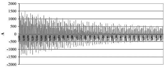
Picture 6. Current flow for the fourth harmonic
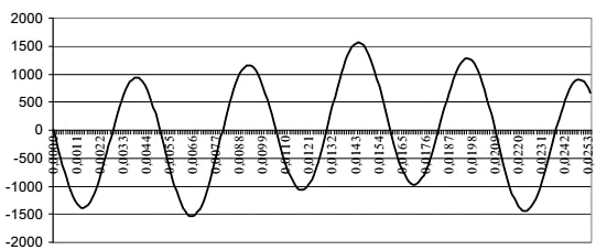
Picture 7. Current flow for the fourth harmonic for the first 25ms
To determine the maximum peak of the current, we need to analyze picture 7, from which we can see that the peak is 1581 A and it is in the 0.0140 second.
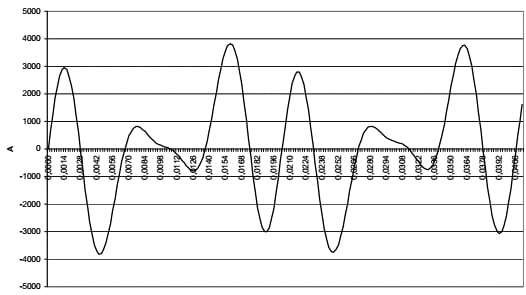
Picture 8. Total current flow for the first 25ms
We will need the total current (sum of the two currents) because that is the main parameter for sizing the switch. The total current is 3812 A, and from the diagram on picture 8 we can see that the system has that value in the 0.0044s.
Voltage measurements
In the following section we will present the voltages in the system during turning on the system.
voltage measurements system
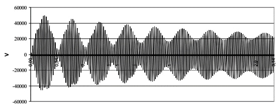
Picture 9 Voltage on C3
From picture 9 we can see that the voltage has value of 50991 V in the 0.22s.
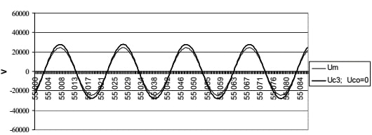
Picture 10. Voltage on C3 in stationary state

Picture 11. Voltage on C3 in transient state
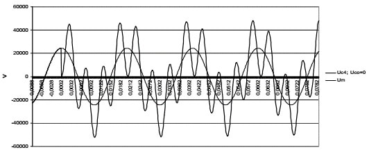
Picture 12. Voltage on C4 in transient state
Conclusion
In our case, we can realize that the maximum value of the current during turning on the battery system exceeds the value multiple times in a small period. The overvoltage of the batteries for the third harmonic is around 51 kV and appears after 0,22 sec. On the fourth harmonic is around 50 kV and appears after 0,18 sec.
It is important to notice that the oscillations are result of the frequency of the system. Their disappearing is actually exponential function of the ratio of R and 2L. As we have stated before, all of these conditions are the worst cases. For all other cases, the results for the current and the voltage will be much better.
What do you think about this article? Do you have something to say about this particular process?