 Choosing a good bus scheme is vital for operational reliability, safety and redundancy of power supply system.
Your fellow electrical engineer K. tries to discuss busbar layout and busbar schemes as per the design of a typical substation.
Introduction
Busbar(s) consist of incoming and outgoing circuits with a common point. Every circuit connected to a busbar scheme has its separate incomer, circuit breaker, isolator, potential transformer, current ratio transformer and associated switchgear. These components are arranged in a special sequence so as to trip a specific circuit in case of an abnormality.
Busbar scheme is selected keeping in mind the following important factors:
- Reliability expectations of the system
- Flexibility in intended operations
- Maintenance plans and feasibility
- Cost analysis
- Real state availability
- Future plans for the extension of substation
- Fault localization plan
- Protection schemes
- Overhead hazards like lightening, air pollution and weather
Common busbar schemes
Different busbar schemes are favorable for different substations. A single substation can have more than one busbar schemes installed. Details of some common busbar schemes are discussed in the paragraphs below…
Single busbar scheme
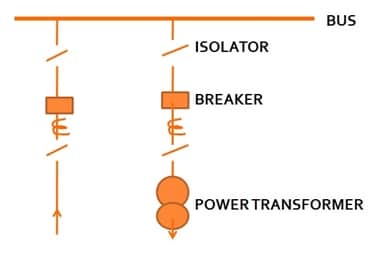
This is simple busbar configuration and one busbar acts as a common point for all circuits. One circuit breaker controls the operation and isolator acts as the only isolating device. Single bus scheme is sectionalized to keep the faults and abnormalities localized.
Single busbar scheme makes live line maintenance very difficult and time consuming. Circuits need to be de energized before periodic maintenance. Addition or dismantling of any circuit on the single busbar requires the substation to be put off.
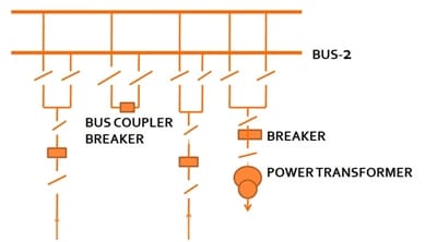
Double busbar scheme
Two busbars are provided with their respective isolators in the double bus scheme. Each circuit can be connected to any busbar isolator and load can be transferred from one busbar to the other when keeping the bar alive. Double busbar scheme is essential where a lot of circuits need to be merged and a highly variable load demands versatile load flow.
Double busbar scheme is suitable for large substations fed by large power stations. Usually one bar is declared reserve and operations are focused on the other busbar. Double isolators become necessary for fault maintenance and breaker handling.
This scheme is suitable for heavy load substations and interconnecting substations for transmission lines.
Double busbar scheme is highly reliable, redundant, flexible and high rated scheme. Maintenance and commissioning cost becomes a little high in case of double busbar scheme.
Three busbar schemes
Problems associated with single and double busbar schemes can be overcome by introducing another busbar known as transfer bus. In case of breaker maintenance, respective feeder(s) is transferred to the transfer bus before commencing the maintenance.
This scheme is suitable for high redundancy applications and is widely used in high priority substations. Strategic feeders are mostly managed by three bus scheme of associated busbars.
Three bus bar scheme offers better load management and control of protection system. Maintenance and commissioning cost is high due to an additional busbar.
Ring or mesh scheme
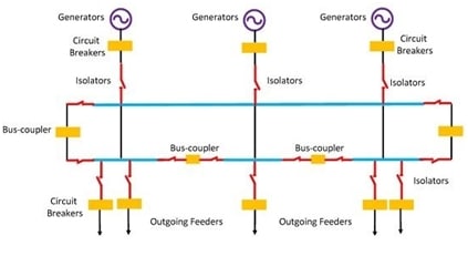
Ring busbar scheme is most widely used busbar scheme in modern substations. Ring or mesh busbar scheme has two circuit breakers for every circuit and maintenance of any circuit breaker can be performed without compromising the supply of the associated feeder(s).
Any fault on the ring is sectionalized by the circuit breakers and ring becomes incomplete till the fault clearance.
Similarly the feeder faults are also bypassed and ring is completed till the feeder fault is cleared and is energized. High redundancy and backup availability makes the ring busbar scheme a perfect choice for power plants and step down substations. Ring system is widely used in USA and United Kingdom along with other major countries.
Different ring schemes are used such as:
- Simple ring busbar scheme
- Rectangular ring busbar scheme
- Circular ring busbar scheme
- Zig-zag busbar scheme
There is a potential disadvantage of ring busbar scheme i.e. complex relaying and breaker trip mechanisms.
Selection of appropriate busbar scheme for a substation
Busbar scheme is a matter of choice made by extensive calculations and load management expectations. Following points are extremely important and should be considered before selecting the busbar scheme for a substation:
- Busbar configuration should be kept as simple as possible. Complex schemes give rise to confusions which may, in turn, cause accidents and performance lapses.
- Routine maintenance should be possible without affecting the power feed. Redundancy for routine maintenance is a must have for every power substations.
- Busbar configuration should pose minimum risk to the maintenance teams.
- Busbar scheme should be economical and expandable.
Further reading
More information about MV busbar schemes can be obtained by referring to the following literature
a. ELECTRICAL PW DIST SYS (page 156 and onward) by KAMARAJU.
b. Power System I (Page 8-50) by U.A.Bakshi and M.V.Bakshi.
helo