Check Nasir’s 7th article from his back to basics series about transformers! Don’t hesistate to send us works, testimonies, personal opinion, reviews or tutorials by mail. We’ll be glad to publish it here.
Definition of a multiple winding transformer
A Multiple Winding Transformer can be defined as the one which has more than one primary or secondary windings connected to each other in some special type of configuration in order to provide the required output voltage levels or drive a number of loads at the output.
This can be referred to as one special characteristic of the transformer, as transformers are quite versatile devices and usually much advanced operations need to be accomplished with them rather than driving merely one output from a single primary coil.
Multiple Winding Transformers are also known as “Multiple Coil Transformers” or “Multi Wound Transformers”.
Principle of a multiple winding transformer
The operating principle of a multiple winding transformer is exactly similar to that of a simple transformer having one primary winding and providing magnetic flux to its one and only secondary coil at the output. If there is more than one coil at the input terminal, all of them will be given the alternating source voltage in the similar fashion, and would be linked through one and the same iron core to the two or more secondary coils at the output. In this way, an alternating magnetic flux would also be produced in all of the secondary coils, which mostly is equal in magnitude, and the voltage can also be obtained according to the requirements. For example, a multi wound step up transformer can be made, and so a step down transformer also.
If we want to drive more than one output, i.e. if we have a number of loads, then the transformer can still be connected such that secondary winding is divided into number sub windings, each driving an independent load at its ends.
The thing that should be noted here is that, since all the coils primary are connected through a common iron core to their secondary coils, so due to Faraday’s Law of Mutual Induction, each individual sub coil would have the same number of voltage per turn, that is, its ratio of primary turns to secondary would still be equal to the ratio of primary voltage to secondary voltage, as for a usual transformer.
So each secondary coil produces the amount of voltage which is directly proportional to its number of turns, since all the coils are electrically isolated and magnetically linked to each other, and to the primary coil as well.
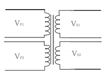
As in the above figure, the two individual primary coils can be connected in series with each other to give a higher primary supply voltage, or the same thing can be done at the other end by connecting the two separate secondary windings in series with each other to achieve a higher supply voltage at the output instead of two individual small voltages. Such Connections will be known as Series connections of the windings.
Similarly, the two or more windings can be connected in Parallel as well to achieve lower voltages but higher currents, as we know that the voltage remains the same in parallel, but the current adds up. Other than these two configurations, the coils can be used as they are in the above figure to drive two individual circuits.
Another configuration of multiple windings is the center tapped transformer in which just the secondary winding is divided into two windings exactly at its center point such that we can get two equal and opposite voltages, with the center point marked as neutral. So a number of configurations can be used to achieve the desired voltage and current levels, or to drive multiple output circuits.
Next post will be on Dual Voltage Transformer. It’s a special type of transformer which gives two types of voltages at the output. In the next post we will explore it and will see what the applications of Dual Voltage Transformer are.
Nasir.