The phenomenon called wear out potential is caused by the current that flows when single-phase earth fault occurs. The analysis of the current flowing during earth fault in the network, could be easily done with α, β, 0 components of the voltage and the current by using Laples’s transformation and complex amplitudes.
For the majority of the distributional networks, it could be considered that the elements in the network have the same parameters for both α and β sequences. The following propositions are taken into consideration in our case:
- the generator and the middle voltage networks are without own sources and completely distributional;
- between the transformer and the middle voltage networks there are two transformations.
Methodology of calculation
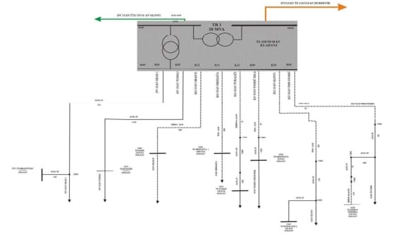
In our case, we are using a test network with one pole schematic presented on picture 1.

Picture 1. One pole schematic of the test network
We will also need the parameters for the transmission line and the cables.
Cable parameters
- frequency: 50 Hz
- magnetic permeability of earth and air: 1.1Ω/m
- sheet resistance : 1.1 Ω/m
- resistance of the extent of the grounding on the cable’s end: 50 Ω
- middle diameter of the cable’s sheet: 0.059 m
- earth specific resistance : 50 Ω
- cable length: 0.3 km
Air transmission line parameters
- grounding post resistance: 13,4 Ω
- frequency: 50 Hz
- earth specific resistance: 100 Ω/mm2
- protective rope specific electrical resistance: 0,945 Ω/mm2
- total number of spans: 76
- length of spans: 0.2828 km
- grounding impedance B: 0.241 Ω
- voltage level: 110000 V
Calculation of the potential and results
According the calculation methodology, with the given parameters, we get the following values presented in table 1, for our specific scenario.
| Data | Value |
| Distance between fictive wire and the protection wire [De] | 930.5525 |
| Protection wire active resistance [p.u] | 0.0195 |
| Protection wire inductive resistance[p.u] per unit | 0.7841 |
| Impedance of the cable | (0.0195 + 0.7841i) Ω |
| Impedance of the cable between two posts | (0.0055 + 0.2217i) Ω |
| Transfer constant | (0.1330 + 0.1295i) Ω |
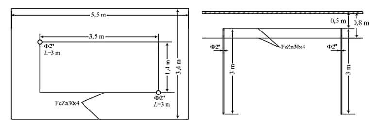
Thanks to those results, we can note that we will need additional change in the existing grounding system. The additional upgrade is actually a PRP2 type grounding system, and it is presented on picture 2.

Picture 2. Additional upgrade to the existing grounding system
According the predictions for the future developments of the power system, we have to think of upgrading the grounding systems in the other parts of the network. The short circuit values in the system will rise for about 60%, so the biggest problem will be the weared out potential significant increase. The only way to avoid is to make the necessary upgrades to the grounding network.
Conclusion
The mathematical model and the methodology, gave us the possibility to conduct an analysis regarding the human’s life. In the design phase of a new power system, we must take into consideration the resistance of the ground and the grounding, by just calculating with the mapping method, or the analogy method.
In our case, some recommendations regarding the grounding system have been given. The time for which the current must be conducted into ground is limited to 0,1s, with maximum limit of 300 V for the voltage.
Also, a modification of the grounding system should be done. The grounding system can be upgraded with additional rectangular contour with the following dimensions 5,5×3,4 m, buried on 0,8 m depth. With this upgrade, we are going to lower the voltage on 169 V, which is in satisfactory limits according to all standards.
Thanks for your attention,
Mile