Hi there, here’s the last but one part of Nasir’s tutorial on transformers. The last one will be about “3 Phase Transformers”. Hope you’ll enjoy it and find it helpful.
Introduction
Current transformers can be defined as the type of instrumental transformers which are used to convert very high currents which can burn or cause damage to measuring instruments like ammeters or other small devices like relays, into lower current values, which are in direct proportion to their higher, primary current values.
In this way, current can be easily measured through the device, and as it is directly proportional to the original high current, the true and precise values of current can also be found without damaging the instrument.
The secondary current differs in the phase angle from the primary current in a very small value which can almost be approximated to zero if the direction of the connections are appropriate.
On the basis of the output supply, the current transformers can be classified into two categories:
- Measuring Type Current Transformers
- Protection Type Current Transformers
Measuring Type Current Transformers
If the output of the current transformer is used to provide protection to measuring devices, electric meters and other such instruments, then the transformer is known as the measuring type current transformer.
Protection type Current Transformer
If the output of the current transformer is used to provide the signal to protective relays and other such devices for their correct operations under steady state and transient conditions, then the transformer is known as protection type current transformer.
Depending upon the range of current that a current transformer can measure, they are of 3 types:
- Ring Core Current Transformers: Can be used to measure current from 50 Amperes to 5000 Amperes.
- Split Core Current Transformers: Can be used to measure current from 100 Amperes to 5000 Amperes.
- Wound Primary Current Transformers: Can be used to measure current from 1 Ampere to 100 Amperes.
Construction and Working Principle of a Current Transformer
Like the conventional transformers, a current transformer also consists of three basic parts that are the Primary winding, a magnetic core and the secondary winding. The basics of the working principle are also the same, i.e, when current is supplies to the primary winding, it produces an alternating flux in the core, due to which an alternating current is also induced in the secondary coil.
The thing that is different from conventional transformers is that in case of a current transformer, the primary winding consists of only one or very few turns of the coil, which can be wrapped around the core or just a wire passing through its center. But the secondary winding consists of several turns and is wrapped around the core in this way:
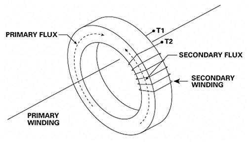
The core is chosen of a low loss magnetic material on which the secondary winding is wound, so that the flux density is low and the current can easily be stepped down to the required level.
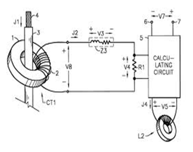
The secondary winding is then connected to the output measuring device or any other device to which we had to supply the output.
This connection is made as shown in the figure below:
Applications of a Current transformer
- Current transformers are used for measuring and monitoring currents, usually of very high values.
- On buildings whose meters have to measure currents higher than 200 amperes, these current transformers are used there to drive their electrical watt meters.
- These are also used to keep track of the current readings on power grid stations.
- These are used in relays for their driving and proper operation of the circuit.
In the next and final post we will have a look at the three phase transformer. Till now we have looked at the different types of single phase transformers. In the coming post we will throw some light on the three phase transformer. Till then take care.
Nasir.
An addendum:
How can you recognize a CT for measurement and a CT for protection ? What’s the difference ?
-the one for measurement (i don’t know the correct Englisch terms) can go into saturation so that you don’t destroy the measerement device. In Europe they are class 2 or 3.
-the others for protectection can NOT go into saturation, otherwise your protection device would not trip in time or not at all. In Europe they have a higher class: 5.
Least but not last, you have to whatch out for the power VA that it can give. The longer the distance between CT and device, the higher the VA’s must be.
Best regards,
Hans Huysmans
(Belgium)