Hi this is Steven Mill! I’m back with a back to basics article about condition monitoring of the transformer. Hope it will help y’all!
The transformer is the most crucial part in electrical distribution system as it is the most expensive equipment in an electrical distribution system. If a transformer fail unexpectedly, not only it will affect the electrical supply but also it will cost you time and money. Hence it is important to detect early sign of fault to avoid power outage and extra cost.
In this article, we will discuss several techniques used to monitor the condition of the transformer. Those techniques are:
- Acoustic Monitoring
- Infrared Monitoring
- Dissolved Gas Analysis
- High Performance Liquid Chromatography
- Partial Discharge
- Frequency Response Analysis
- Power Factor
- Winding Resistance
- Core Insulation Resistance
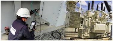
Acoustic Monitoring of the transformer
It is clear that if the load of the transformer increases, the noise will also increase. Hence several measurement is needed to monitor transformer’s performance by measuring the noise such as [1] :
- The basic of noise level, ie. When the transformer is new.
- Changes in noise level over time, at a given load.
- Relative level of noise compared with the background noise.

Figure 1. Acoustic monitoring | image: mitrasgroup.com
Infrared Monitoring
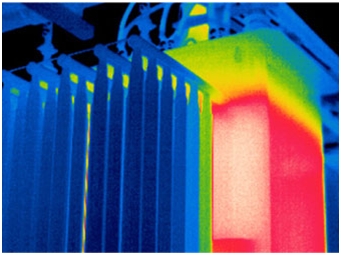
Infrared monitoring is the method to measure the performance of the transformer by detect the hotspots that occur because, for example, improper cable connection or winding failure.

Figure 2. Infrared test detect the hotspot of the transformer | image: ltl.ca
Dissolve Gas Analysis (DGA)
Whenever oil transformer experience abnormal thermal, electrical stress, and other faults, several gases are produced due to decomposition of transformer insulation oil. When the fault is major, the production of the decomposed gas are more and they get collected in Bucholz relay. However when the faults are not significantly high, the gases will get enough time to dissolve back in the oil. Hence it is necessary to analyse the quantity of different gases dissolve in transformer.
By using interpretation technique (Key gases, gases ratio, or data mining) we can deduce fault indication by interpreting the DGA tests result. The fault that could be detected by DGA tests are:
- Electrical discharge
- Partial discharge
- Thermal fault in oil
- Arcing in Tank tap changer
- Overheating of cellulose
- Degradation of cellulose by electrical fault
High Performance Liquid Chromatography
This method is developed in order to overcome DGA insensitiveness when lower temperatures (100 to 1300 C) are concerned. The method correlates well with cellulose aging determined from Degree of Polymarisation (DP) measurements [2].
DP measurements represents the length of the cellulose chain while HPLC identify the presence of furanes and furfurans, created as the length of the cellulose chain shortens, as part of the aging process.
HPLC has been found to be sensitive in detecting aging at relatively low temperature and to provide strong evidence of aging when transformers have been overloaded [2].
Partial Discharge
Partial discharge is electrical discharge which does not completely bridge the two electrodes. On a transformer, partial discharge can occur in void of winding material or in gas bubble in an oil. Partial discharge on the transformer can be detected by DGA test. However, a specific particular discharge test is performed to obtain specific location of the fault and more reliable result.
A partial discharge measurement consist of:
- Transformer being tested
- Coupling capacitor
- High voltage supply
- Partial discharge detector
- Software for analysis
The partial discharge is measured by analysing the voltage drop at the transformer line terminal. This voltage calculated further to measure q, the apparent charge of the partial discharge. The detail of the partial discharge measurement will be explain specifically in other article.
Frequency Response Analysis (FRA)
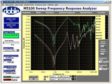
Frequency response analysis is used to detect fault of the transformer, particularly to determine the displacement of the winding.
Any electrical equipment always consists of resistance, inductance, and capacitance RLC that is a function of frequency. The RLC impedance versus frequency characteristic is then used to assess electrical and mechanical condition of a transformer. Laboratory test have demonstrated the sensitiveness of this technique.
FRA can be used to detect mechanical damage and winding deformation of the transformer after fault happen. If short circuit occur in the transformer, it can suffer heavy mechanical damage from the very large electromagnetic force. Winding deformation also can be caused by lightning or system switching. After such an event, the engineer need to know whether it is safe to re-energise the transformer by doing FRA test.
FRA is normally used to analyse [1] :
- Change in the response of the winding
- Difference between the responses of the three phase of the same transformer
- Differences between the responses of the transformer of the same design
Option require that FRA has been previously performed on the transformer, whilst option b and c doesn’t.

Figure 3. FRA of a new transformer | image: globecore.com
Power Factor
Power factor measurement is performed to assess the dielectric condition of the transformer. Power factor testing is an effective method to detect and help isolate conditions such as moisture, carbonization, and contamination in bushings, windings and liquid insulation. In addition to power factor testing, transformer excitation current measurements will help detect winding and core problems.
However, the fact the measurement is an overall quantity for the winding and therefore it is practically impossible to determine whether there is a problem of the whole winding, e.g. contamination by sludge or carbon deposit, or localised fault.
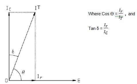
Power factor test is performed by applying voltage and measure the leakage/loss current of electrical insulation [3]. The leakage comprises of two components:
- Resistive current (Ir)
- Capacitive current (Ic)
Polarisation Spectrum
This technique is used to measured water content in the paper in an oil-paper insulation system and is increasingly being seen as a more reliable indication of dryness of the transformer than moisture in oil measurements.
The test is performed by charging the transformer dielectric by 2000VDC voltage for a particular charger time, discharged for half time, and then the peak and initial slope and the recovery voltage are measured. The dielectric is then fully discharged before a new measurement is made for a different charge time. Measurements can be made for charge times from 20ms to 5000s. The condition of the dielectric is characterised by the dominant time constant for the peak recovery voltage and by the characteristic slope of the initial slope versus peak recovery voltage plot [1].
However there is uncertainty of the results if the test is performed in a few very old transformer as oil acidity and paper degradation can complicate the result.
Winding Resistance
This test is performed to check the transformer winding, terminal connection and tap changer, and also to calculate the load loss value. Loose connections and high contact resistance can initiate increasing levels of ethane and or ethylene.
Winding resistance can be measured using micro-ohmmeter. The results then compare with factory measurements with a correction factor is needed. The following formula is used to compare the result:
Where,
Rs = Resistance at the factory reference temperature.
Rm = Measured resistance
Ts = Factory reference temperature (usually 750 C)
Tm = Temperature at which measurements were taken
Tk = A constant, 234.50 C for coper, 2250 C for aluminium
Core Insulation Resistance
Additional core ground can be detected by DGA. However, core insulation resistance is performed when the winding resistance shows that all of tap changer and connection contacts are in good condition whilst DGA test show significant proportion of ethane, ethylene, and possibly methane.
The test is done by disconnecting the intentional ground. The resistance is measured in mega ohms by a DC megger or may be determined from calculation. Make sure to always earth the core and the tank before measuring the insulation resistance. Next, short circuit the both winding terminals of the transformer. After that, core insulation resistance is determined by measure the resistance between each winding and all other earthed windings.
The following table show the condition of the core insulation resistance for different measured readings [4]:
References
[1] D. Hoyle and R. MacKinlay, “Transformers 3 (Electrical Performance Testing),” in Asset Management, Maintenance & Condition Monitoring, Newcastle Upon Tyne, Newcatle University, 2015, p. 7.
[2] P. D. J. Allan, “Transformer Magnetic Circuit,” in Transformers, Newcastle, Newcastle University, 2015, p. 30.
“megger.com,”
[3] Megger, [Online]. Available: http://en.megger.com/getmedia/7050fe9b-7fdc-45a4-ba86-4d4f2cb8b114/Transformers_AG_en_VO1.PDF/. [Accessed 17 April 2016].
[4] “IEEE Guide for Diagnostic Field Testing of Electric Power Apparatus Part 1: Oil Filled Power Transformers, Regulators, and Reactors,” IEEE Standard 62-1995, 1995.
Thanks again for reading me!
Steven Mill
Did this article helped? Do you think it lacks information? Tell us in the comments below.


This reduces the shutdown time
This is an excellent system that you have developed here Steven, seems very comprehensive and easily applied to all sorts of different transformers.
I have been using transformers since long time and the above explained is just amazing so simple and clean, I guess the aged transformers measurement can also be 150 < R < 1500. This will create more power. I have used it before.