
From then on, he kindly decided to help providing the blog with material, and his 1st attempt is about power factor correction of networks.
Tell this young man from Macedonia what you think about it below!
Introduction
The production capacity of the thermal power plant REK Bitola which is located in the city of Bitola, Republic of Macedonia, represents approximately 75-80% of the overall production of electric power in Macedonia. I made measurements and tests for the consumption of the coal mines that are the two main units of this thermal power plant. My main focus was the middle voltage network, because on this part of the network are the most consumers, that are relevant for this experiment.
The power plant is divided in two parts ( two separate coal mines, Suvodol and Gneotino ). The mine Suvodol has two transformers of 31,5 MVA while Gneotino has only one with the same nominal power. The installed power for the mine Suvodol is 61,293 MW while for Gneotino is 32,234 MW.
These are the starting points for my experiment. In table 1 below, I am going to present the installed and peak power of the machines in the coal mines of REK Bitola.
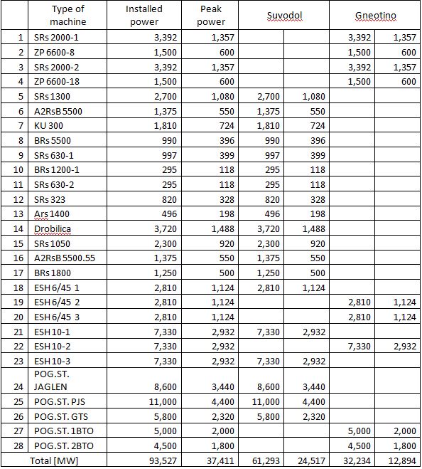
Table 1. Installed and peak power of the machines
In the article I have used the measured quantities of the active and reactive power for year 2015. The measured quantities are gathered from the power meters of MEPSO and ELEM (two national power companies).
From these measured quantities, I determined that Suvodol spent more reactive power and worked with cosφ=0.5954. It was the same situation with Brod Gneotino. The mine spent more reactive than active power and worked with cosφ=0.6496.
The reason for this is mainly the fact that the network is full of transformers with 6/0,4 kV ratio, asynchronous machines without PWM are used and of course at the end the long length of the power cables.
Electric power consumption in real situation
In this part of the article, I made measurements of the active and reactive power and the power factor on the nodal point B6 where all the consumers are connected. The measurement was made with Fluke 41B instrument.
On picture 1, I have presented the values from the measurement. These measurements are made for the coal mine Suvodol.
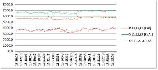
Picture 1. Active, reactive and apparent power in nodal point B6 in coal mine Suvodol
From the given values, we can easily see that the active power is much lower when compared to the reactive power. On picture 2, I have presented the power factor.
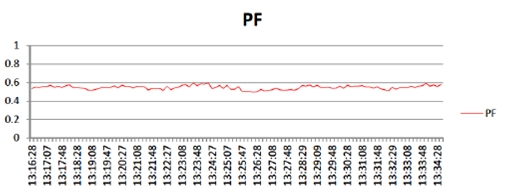
Picture 2. Power factor in nodal point B6
The same measurements were made for the other coal mine Brod Gneotino on the nodal point A12. On picture 3,4 and 5 you can see the diagrams for active power, reactive power and power factor on that specific nodal point.
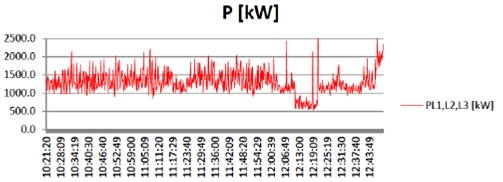
Picture 3. Active power on nodal point A12
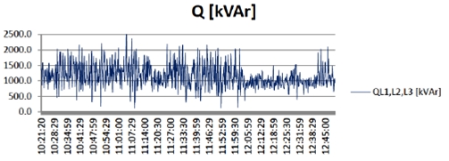
Picture 4. Reactive power on nodal point A12

Picture 5. Power factor for nodal point A12
As we can see from the given measurement results, Brod Gneotino has better power factor, mainly due to the fact that the lengths of the power lines is much shorter, the asynchronous motors have PWM regulation and the fact that three mining machines have synchronous motors instead of asynchronous.
Ways to compensate the reactive power
As addition, I made one MATLAB Simulink analysis of the load. I analyzed the load of the mining machines SRS 2000/1 and SRS 2000/2, with installed P=6.0 MW and Q=2MVAr, respectively. These machines are connected to the nodal point A06 in the system of the coal mine Brod Gneotino.
In the pictures below, I will present the diagrams for non compensated network and compensated network.

Picture 6. Values of active and reactive power in non compensated network

Picture 7. Values of power factor in non compensated network
For compensation, I used static compensation of 120 kVAr, and also static filters for the 3,11,13 and 24th harmonic, because it will improve the voltage in the network. The condition of the network improved drastically, and we can see that from the following diagrams.

Picture 8. Active and reactive power after compensation

Picture 9. Power factor after compensation
Conclusion
From all the facts that were brought up in this article, we can see that if REK Bitola can compensate the reactive power and increase the power factor up to cosφ=0.95, the reactive power will be compensated up to 33%.
Because the consumption of reactive power for 2015 is 9571159 kVArh, which costs 3.399.131 EUr, the savings would be nearly 1.121.713 EUr, which is not a sum that should be neglected.
All that has to be done is:
- Local compensation on all 6kV and 0,4 kV machines
- Highly efficient asynchronous motors should be used
- Synchronous machines should be used in order to fix the power factor
- On the 6kV side of the transformers, passive and active filters should be implemented in order to decrease the influence of the harmonics
Thank you for reading my very first article for the EEC blog!
Mile.
What did you think about Mile’s work? Tell him below!
At low power factors, can we use ordinary watt meter or we have to use any special type watt meter.