What about a new article from our fellow electrical engineer Jesús Pérez Díaz? Today he tells you about Ground fault protection so if you’re interested in this topic, enjoy!
And if you have knowledge to share about it, write a comment or an article. You just need to send us a mail.
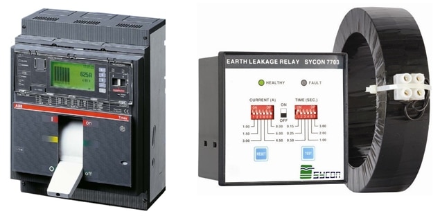
ABB Circuit Breaker & Ground fault relay | image: ndu.cl
Introduction
Statistics have shown that electrical faults involving Ground are more likely to occur than any other one. A ground fault happens when any of the phase conductors (also known as: hot, live, and line) gets on contact to ground or any grounded part such as a grounded motor frame. It could take place because of a reduction of insulation, cable damage, overvoltage, an accident originated by people or incorrect wiring, and bad equipment operation.
The short circuit current resulted from a ground fault will depend of the neutral grounding type and the impedance of the path from the fault location to the source (Distribution transformer / generator). A ground fault can be really dangerous, producing an arc blast and fire, burning and giving electrical shock to people located near the failed equipment. Solidly grounded and low impedance neutral scheme require fast clearing for ground faults but coordination with the other devices should be achieved.
Ground Fault Protection: when is it required?
Standard codes establish the criteria for applying ground fault protection, also client and engineering practices must be taken into account. As summary, National Electric Code indicates that Ground Fault Protection is needed for systems that meet all of the following:
- Solidly wye
- More than 150 V Line-Neutral but less than 600 V Line-Line
- Main disconnect device is rated 1000 A or greater
Ground Fault Protection: when is it omitted?
It is not required for:
- Systems that don’t comply with all the above conditions
- Firefighting pumps
- Equipment process where a shutdown increase hazards
- Single phase circuits
- Delta systems
- Resistance or impedance grounded systems
Ground Fault: how can it be detected?
There are different ways to detect ground faults using current transformers. They consist in monitoring the current that flows on all feeder conductors and determining the possible unbalance that means a ground fault.
Residual Connection:
It considers 3 current transformers (or 4 if neutral conductor is included) wired to a relay (or sensor) which sums all the secondary currents.
Theoretically, the result of this sum should be zero even though a fault occurs on phase conductors (without ground) or an unbalanced load is present, only faults involving ground result on a variation of total current, so that is interpreted as a fault. Take a look at figure 1.
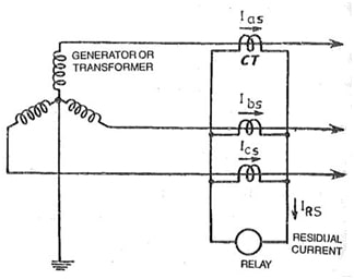
Figure 1. Residual connection | yourelectrichome.com
Core balance current transformer:
It implies only one current transformer core balance type. All phase and neutral (if it’s used) conductors are wired through de window of the current transformer.
The total flux sum is also zero even though unbalance load and any fault excluding ground take place, so any current detected by the relay correspond to a ground fault. See figure 2.
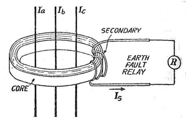
Figure 2. Core balance current transformer | yourelectrichome.com
Ground Return:
Ground Return is another way to detect ground fault and consists on placing a current transformer at the ground connection of the neutral. Any returning current through this connection represents a fault so relay should trip the circuit breaker.
Considerations and typical settings
Ground fault protection settings and its calculation are determined in a different way of phase overcurrent protection. Ground fault currents aren’t transmitted by power transformers, specifically in delta/wye and delta/delta connections.
So, it could be said that the calculation and analysis for determining the proper setting are totally independent for each system voltage, making it faster than normal overcurrent protection, avoiding time delay from the load to the source through all the voltage levels.
In that sense, the calculation is easier and simple, but it needs to consider the following:
- Ground fault protection setting has a lower pickup than phase protection settings since is independent of normal operation currents.
- If the circuit to be protected feed an individual load, then the pickup can be low such as 5-10A or in the range 10-100% of the phase trip setting (overload / long time).
- If the circuit to be protected feed various loads, then the pickup must be enough to allow the ground fault clearing from downstream devices. If a downstream device doesn’t have ground fault protection, then its phase settings must be used to coordinate with the main service (upstream circuit breaker or incomer). This assure that main circuit breaker shouldn’t trip immediately by ground fault protection if the fault is located downstream of branch devices.
- The pickup setting may be same for all series devices, the coordination is succeeded by time settings, giving enough delay to consider downstream tripping, clearing time, and safety margin.
- Time setting of ground fault protection for main services (Panelboard, MCC, Swtichgear, Switchboard, etc.) shouldn’t be less than 0.1 seconds. For individual loads should be enough to avoid tripping by inrush currents.
Ground Fault: sample Calculation
Consider the following Switchboard (figure 3) and input data to determine the ground fault setting of the main service (CB1) and motor branch circuit (R1) assuming that the other branch circuit doesn’t have ground fault protection (CB3).
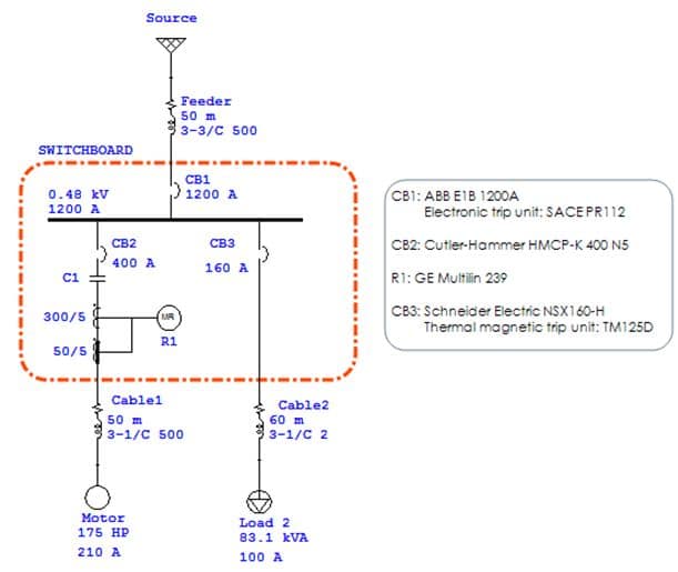
Figure 3. SLD of Sample
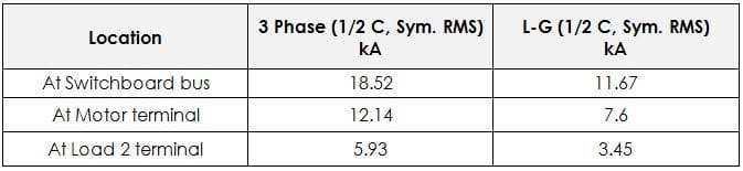
Short circuit currents (Input data)
Let’s start analyzing the motor branch circuit.
Overload protection of motor is around 115% of FLC: 241 A. (see: https://engineering.electrical-equipment.org/electrical-software/lv-motor-protective-device-settings-video-tutorial.html)
Since it is an individual load, ground fault protection should be between 10-100% of the phase overload setting.
Pickup = 241 A * 10 % = 24.1 A
Time delay is selected as 0.1 second to allow inrush current and avoid false tripping. Take a look figure 4 for the obtained protection curve.
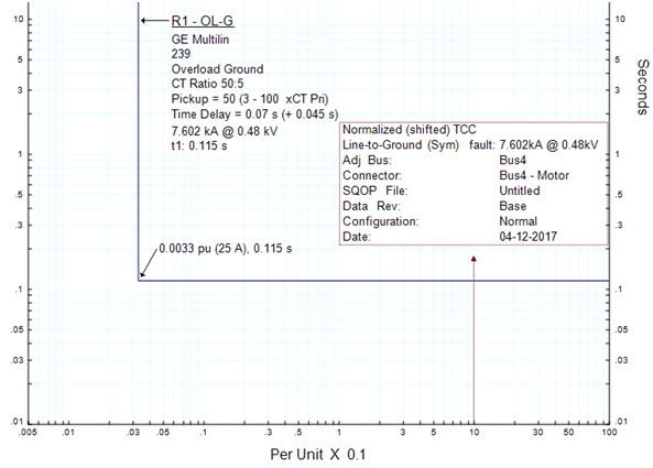
Figure 4. Ground fault protection curve R1 (Motor branch circuit)
For main service, minimum ground trip setting of the indicated electronic trip unit is 240 A, which is the 20 % of overload setting (1200 A). Time delay could be around 0.3 seconds in order to coordinate with downstream devices. These values need to be verified by the protection curve of downstream devices.
Let’s view the ground protection curve of the CB1 (incomer) with the above settings against the one of the R1 (motor branch). See figure 5.
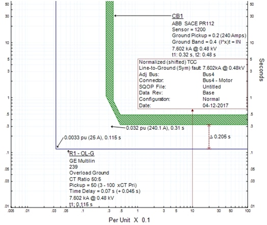
Figure 5. Ground fault protection curve R1 (Motor branch circuit) and CB1 (Incomer)
It doesn’t seem to be troubles!
Now, it’s time to compare it with the curve of CB2, remember that last one doesn’t have ground fault protection function. So, CB2 phase protection curve must be used! See figure 6 and 7.
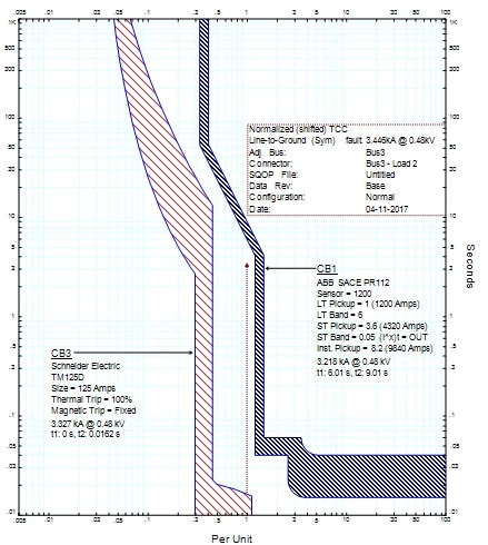
Figure 6. Phase protection curve CB1 (Incomer) and CB3 (Load 2)
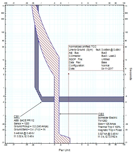
Figure 7. Ground fault protection curve CB1 (Incomer) and CB3 (Load 2)
As can be seen, there is coordination between both Circuit Breakers when a fault at load terminal occurs (CB3 trips before CB1), so the selected settings are acceptable and validated.
Thank you for reading,
Jesús Pérez Díaz.
Awesome! Do not hesitate to ask questions or give your remarks to Jesús, he will be happy to answer.
Figure 7: For fault current values of 0.05 to 0.2 per unit CB1 ground sensor does not coordinate with CB3 phase sensor. Please explain.
Thank you
Hello Samuel, sorry I haven’t seen this since now. That is a good question
Ground Fault protection of CB1 should be modified in order to coordinate with CB3 (total coordination) instead of is shown in figure 7 (Partial coordination). This could be acceptable if there is no settings to comply with total coordination, or when all the possible ground currents will be in the coordinated part of the curve. I will send an email in order to update the figure.
Regards,
Thanks Jesús for the efforts. I concur with Samuel’s comment and would love to hear your expertise on this.
Please check my response.
I need to know the answer to Samuel’s comment.
Please check my response
Sir,
In Fig.7, there is an overlap between CB3 & CB1 at current 0.06 to 0.3 pu. Please clarify.
please check my response