Hi everybody, it’s Steven Mill. I know it’s been a while since I haven’t published an article on the blog, but here I am. Today I want to tell you about underground cable faults and how to detect them. Ready?
In a power transmission and distribution system, cables serve the primary purpose of transmitting electrical energy from one point to another. A fault at any section of the cable system significantly reduces the functionality and integrity of the whole setup. This situation significantly escalates with underground cables, due to the location. With the power systems growing rapidly over the years, the number and length of cables has increased over the years…
Other than the obviously higher cost than overhead cables, the location gravely affects cable fault detection, location and attendance. Well, unearthing the whole cable for checks, while it may work, is expensive and unnecessary. The challenge therefore is to find fault detection methods that are less ‘evasive’.
Detecting underground cable faults: the whole process
The following are the common ways to detect underground cable faults:
Sectionalizing
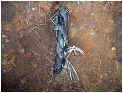
This is perhaps one of the most rudimentary and destructive ways to detect cable faults.it involves digging up the cable, and cutting it into sections, followed by inspecting and testing each section for faults.
Thumping
It involves introducing a high voltage (25kV) on one end of the cable to induce a high current arc in the faulty cable. The arc occurs at the fault location, and at such a high voltage, it is high enough to cause a thump sound that is audible above the ground. Well, suffice to say there are drawbacks:
- One, it is hard to access such high voltage for low-medium priority testing, though there are commercially available surge generators.
- Secondly, the mere fact that there are better methods out there. Thirdly, the method is cumbersome, and ineffective to use for long cable lengths.
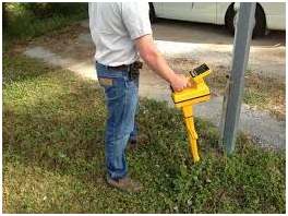
Transmitter and receiver method
It consists of an AC generator that supplies the signal current to the underground pipe, and a receiver that detects the electro-magnetic field from the signal current. In many instances, the transmitter also contains information on the amount of resistance that the current circuit carries.
Time domain reflectometry
Also referred to as pulse echo method, enables the tester to measure the distance to any changes in the cable. A pulse of radio frequency is introduced on one end of the cable, and then an integrated timer measures the frequency travel along the cable. The timer stops when the frequency is reflected back.
There are standard values for various materials used in cable construction for various lengths. With this information, the tester can be able to pinpoint the point of disparity accurately based on the time. Do note that a fault changes a cable impedance, and thus, the ability to transit pulses.
The information required for accurate pinpointing include velocity of propagation, maximum distance that can be displayed on the TDR display and pulse width.
Conclusion
Regardless of the method used to detect an underground cable fault, accurate pinpointing of the fault is as crucial. Engineers and testers use microphones and sound amplifiers for an accurate location.
Usually, the acoustic equipment has range interface, or counter, so that the user can pinpoint the area with the highest sound. The assumption is that the sound travels up unimpeded by either roots or rocks.
Thanks for reading,
Steven Mill.
Very nice article! Do you have other advices to give? Share them in the comment section.
Steven thankyou very much for this quintessential article your work is really admireable.
But sir i have little bit confusion if there is short circuited fault(line to ground)
then how TDR will be helpful to trace the fault location.
Good one there.. I’m new here…
Thanks Sir
Measure the resistance of each cable between farther ends, if there is a considerable variation in any one of the cable, that is the faulty one. This method is also used in industries called as “Insulation Resistance Test”.
For more information you can visit: http://www.rklala.com/importance-of-cable-fault-locators/