Let’s hear what more Carlos, one of the member of the EEC, has to say about cable sizing… Share and comment below!
Introduction
In case of medium and low voltage cables, the terms size and efficiency are related to the minimum cross section that is fully in compliace with sizing criteria.
In this regard, three criterias must be met for the selection of the appropiate cable cross section in underground duct banks. These criterias fore cable sizing are: Ampacity, Voltage Drop and Short Circuit.
Cable sizing: ampacity criteria
The ampacity may be defined as the maximum current that can safely flow through a wire or cable. There are several factors that might affect the ampacity of a cable in undergroung duct banks such as: ambient temperature, duct bank thermal characteristic, and the heat generated by the cable itself and by other adjacent cables.
Manufactures of medium and low voltage cables, state ampacity values for all available commercial sizes (AWG, mm2 or kcmil) based on specific conditions regarding to the environment that surrounds the cable.
Typically, manufacturers consider the following conditions: cables are installed in groups of three, soil thermal resistivity (RHO) of 90 °C–cm/W and ambient temperature of 20 °C or 40 °C. If any of these conditions differs to those considered by manufacturers, correction factors should be applied as follows:
Where:
ID: Derated cable ampacity under actual installation conditions (A).
IR: Manufacturer rated cable ampacity (A).
Ft: Correction factor due to the difference between the ambient and cable base temperature.
Fth: Correction factor due to the difference in the soil thermal resistivity RHO.
Fg: Correction factor due to cable disposition in the underground duct bank.
Fc: Correction factor due to the installation of more than three cables within a conduit.
Factors Ft, Fth, Fc and Fg can be found in manufacturer data sheets or other Codes and Standards such as NEC, IEEE and IEC.
Cable sizing: voltage drop criteria
An electrical current flowing through a conductor produces a power loss as well as a voltage drop from the power source to the load.
A simple analysis of the circuit shown in figure 1and its phasorial diagram, can help understand how the cable impedance might negatively impact the quality of power supply to a customer as a consequence of a large voltage drop.

Figure 1. Single line and phasorial diagram – Inductive electrical circuit
From the previous figure, it can be affirmed that the voltage drop is directly proportional to the current magnitude and the cable impedance (see equation 1).
V0V1=(R+jX)∙I
In this regard, considering that the cable impedance depends on its cross section, the cable size must be selected in oder to ensure service and utilization voltages within the ranges established in codes and standards.
For example, in North America, the voltage ranges stated in ANSI C84.1 have been accepted as a reference for the optimal operation of motors and static loads.
Cable sizing: short circuit criteria
Low and medium voltage cables are overheated due to the flow of overcurrents during a fault condition. The heat produced on the conductor by the Joule Effect will raise the cable temperature with the risk of damaging the insulating materials. This is the reason cables must be sized to whitstand short time overcurrents, while the protection system clears the fault.
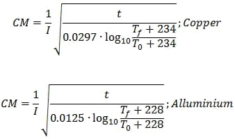
The following ecuations let calculate the required cross-sectional area in Circular Mils (CM) for copper and alluminum cables, ensuring that the insulation will not lose its caracteristic or damage for a known maximum available short circuit current and a total clearing time.
Where:
I: Short circuit current (A).
CM: Cross-sectional area (Circular Mils).
t: Fault Clearing time (s).
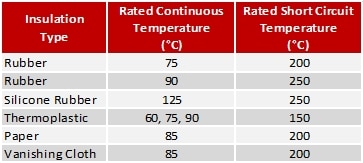
Tf: Rated short circuit current temperature (°C).
T0: Rated continuous temperature (°C).
Values of Tf and T0 can be obtained from Table 1 (Cable Continuous and Short Circuit Temperatures).

Conclusion
Sizing low and medium voltage cables is a very important stage in the design of any electrical system. This task is not as simple as electrical engineers might think.
Therefore, in order to avoid a catastrophe as a consequence of an inappropriate cable sizing, criteria explained in this article are highly recommended to increase the quality, reliability and security of the power supply to any customer.

hello!
What is the effect of paralleling 33kV network and 11 kV network through the 400V circuit?
Good day.
Could you indicate some standards or other references that show the calculations?
Thanks in advance!