
Martin M.’s articles are always very nice and interesting. Today we chose to publich this one, in which he draws a comparison between GIS (Gas insulated substations) and AIS (Air insulated substations).
If you also have great articles like his, feel free to send us a mail. You can write about whatever you want in the electrical field!
Introduction
The last few years have seen tremendous improvement in power generation and distribution. For the power supplier, the most important part is the transmission and distribution control.
Due to the large power demand brought about by a growing population and a robust industrial sector, there is a need for the power supply company to embrace efficient methods. One of the key areas is substation insulation.
There are two primary substation insulation systems in the world, Gas insulated, and Air insulated substations. The following highlights the primary differences between the two.
Gas Insulated Substation (GIS)
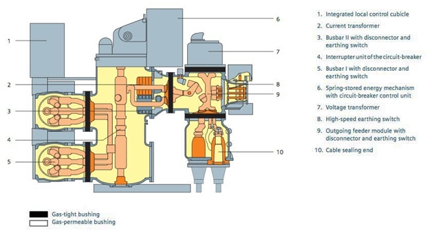
Simply put, in the GIS system, all the live components are enclosed in a grounded metal enclosure, then the whole system housed in a chamber full of gas. Gas insulated substations (GIS) primarily use sulphur hexafluoride gas as the primary insulator. SF6 is non-toxic, maintains atomic and molecular properties even at high voltages, high cooling properties, and superior arc quenching properties.
In addition, is safe. SF6 has superior dielectric properties compared to other gases; thereby provide favourable insulation for the phase to phase and phase to ground moderation. In the substation setup, the gas is contained in a grounded metal enclosure containing the conductors, current and voltage transformers, circuit breaker interrupters, switches, and lightning arrestors.
Working Principle
A point of note is that the GIS contain the same compartments and components as the normal (AIS) setups. The only difference is the insulation medium, and of course the size. The live components and parts are insulated in metal enclosures filled with SF6 gas at moderate pressure. Each compartment housing the live part is gas tight, with respect to each other. This ensures that the gas does not pass to the neighbouring modules, as well as ensure that gas monitoring is simpler and independent. ‘O’ rings are installed at the equipment and enclosure flanges to provide the gas tightness.
Another important installation is a gas monitoring system. This includes an integrated alarm system, automatic tripping, and lockout in case of low pressure due to leakage.
Advantages of GIS
- The earthed metal enclosure makes for a safe working environment for the attending personnel
- Compartmentalized enclosure of the live parts makes for a very reliable system due to reduced disruption of the insulation system.
- By reducing the distance between active and non active switchgear parts, less space is required than in the normal AIS system: this comes in handy in densely populated areas and unfavourable terrain (minimum requirements for an AIS is about 47,000m2, while GIS with the same power properties will require approx 523m2). For the AIS, the highest element is approximately 28m, whereas for GIS you have 11m at the highest point for a 400kV substation.
- Low maintenance requirements due to expedient design and protection against external elements.
- Under scheduled maintenance, SF6 neither ages nor depletes. There is no need to top up the gas levels throughout the equipment lifetime (approx 40 years).
- Quick assembly due to extensive pre-assembly
Disadvantages
- High installation costs compared to AIS systems
- Procurement and supply of SF6 gas can be a problems especially in rough terrain and off site locations. This further increases the costs
- High level of maintenance is required. This requires highly skilled personnel
- Internal faults tend to be very costly and severe when they occur. They often lead to long outage periods. For example, the use of impure gas, as well as leakage due to ‘O’ ring failure, as well as presence of dust can lead to flashovers and explosions.
- Though the gas is quite inert, flash problems can break it down into harmful by-products such as metal fluoride powders. This poses a health hazard such as physical asphyxiation and other respiratory problems.
Applications
In a regular setup, the space between phases and ground to phase is normally very large. This is where the regular AIS come in handy. However, with the growing population, especially the large towns and cities, such large spaces are hard to come by. This is where the GIS is most applicable as the gas provides superior insulation properties compared to air.
Therefore, the substation unit can be contained in a smaller area without any risk of failure. The use of the SF6 thus reduces the space between the phases, and ground to phase. With the use of the gas, the size of the equipment, and consequently the whole substation can be reduced by about 10%, a significant area when you consider the size of substations serving large cities and towns.
Other areas of applications include:
- Underground station: reduces the total area to be excavated, thus cutting on costs
- Offshore-located substations
- Substations situated in rough terrains such as mountain regions and valley
- Highly populated area
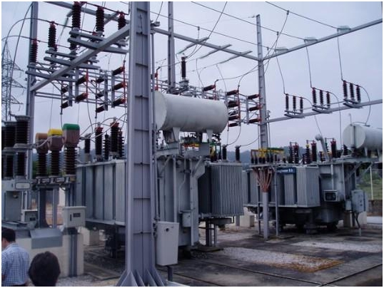
Air Insulated Substation (AIS)
The AIS uses air as the primary dielectric from phase to phase, and phase to ground insulation. They have been in use for years before the introduction of GIS.
Actually, most substations across all regions are AIS. They are in extensive use in areas where space, weather conditions, seismic occurrences, and environmental concerns are not an issue such as rural areas, and favourable offsite terrain.
The indoor AIS version is only used in highly polluted areas, and saline conditions, as the air quality is compromised.
Advantages
- The primary choice for areas with extensive space
- With quality design, the system is viable due to the low construction costs and cost of switchgear
- Less construction time, thereby more suited for expedited installations
- Easy maintenance as all the equipment is within view. It is easy to notice and attend to faults.
Disadvantages
- More space is required compared to GIS
- Vulnerable to faults since the equipment are exposed to the external elements such as human intrusion, pollution, deposition of saline particles, lightning strikes and extreme weather conditions
- More maintenance requirements, thus leading to high costs
- The poor dielectric properties of air, as well as secondary factors such as humidity, pollutants, moisture means that more space is required for efficacy.
Conclusion
For the engineers and technicians, the choice between GIS and AIS depends on the pros and cons between the two. However, for the many substations projects around the world, GIS offers the obvious choice. This is due to the technological and economic advantages associated with GIS over AIS.
Well, the only downside is the global warming issues associated with CFCs. Until the time SF6 is banned, it remains the best option.
Martin M.
What do you think about this article? Is there any other differences, advantages or disadvantages between AIS and GIS?
There are plenty of great advantages to both gas and air insulated substations. These are some great points, thanks for posting.
Good & easy to understand note on GIS & AIS.
We see higher or inflated prices are being quoted by GIS supplier in India & prices of spares are at an exorbitant rate.
Knowledge is with few persons at Utility & even at supplier end creating emergency during breakdown of system.
I feel the advantages of space saving by GIS is getting offset by initial cost itself and cost of services after warranty period
I think the mere mention of GIS safety is not sufficient. This is, by far, the most significant advantage.
Has anyone been killed in a GIS substation? AIS?