Hello everybody, enjoy this article from one of our fellow members of the community! And if you have remarks or questions to ask, do post them in the comment section.
Joining electrical power cables can be as simple as twisting the wires and taping them or more detailed using a variety of inline adapters and connectors. The method used for a particular joint depends on the voltage, type of cable, type of joint, type of connector, application and other factors.
Regardless of the method used, it is important to have the proper tools and materials. Some of the key factors that ensure clean, safe and reliable connections are;
- Using the proper size of the connector for the particular cable
- Proper tools
- Clean cuts and stripping
- Restoring the insulation, armor and outer-sheath
- Proper technique
Typical electrical cable jointing methods
Western union splice joint
This is a straight joint used for small solid cables
- Remove the insulation
- Bring the two conductors to a crossed position and then make a long bend or twist in each wire.
- Wrap the end of one of the wires around the straight portion of the other wire, and then do the same for the other wire. Repeat this for about four or five times.
- Press ends of the wires down close to the straight portions of the wire to prevent the ends from piecing through the insulation tape.
- Insulate the joint using the tape
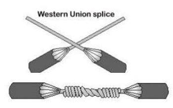
Figure 1: Western union straight joint | image: electricneutron
Rattail joint
The rattail joint is usually used in the junction boxes. It allows the connection of branch or multiple circuits in buildings.
To create the joint,
- Strip the insulation off the ends of the cable to be joined
- Twist the wires to create the rattail effect
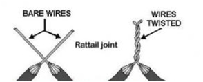
Figure 2: Rattail joint | image: electricneutron
Fixture joint
This is a type of branch joint connecting a small-diameter wire to the large diameter conductor, such as those used in lighting fixtures.
- Remove the insulation
- Wrap the fixture wire around the branch wire
- Bend the branch wire over the completed turns
- Wrap the remaining fixture wire over the bent branch wire
- This can be followed by soldering and taping, or simply taping of the joint.
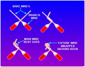
Figure 3: fixture joint | image: tpub
Knotted tap joint
The knotted tap joint is used to for branch joints to connect a branch wire to a continuous wire.
- Remove about 1 inch of insulation from the main wire and about 3 inches from the branch wire.
- Place the branch wire behind the main wire so that three-fourths of its bare wire extends above the main wire.
- Bring the branch wire over the main wire, around itself, and finally over the main wire so that it forms a knot. Wrap the wire around the main conductor in short, tight turns and trim its end.
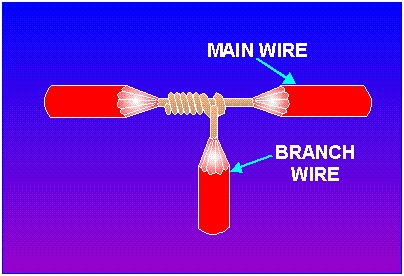
Figure 4: Knotted tap joint | image: tpub
Joints using wire nut and split bolt
The wire nut replaces the rattail joint splice. The nut is usually housed in a plastic insulating casing. To make a joint,
- Strip the conductors
- Place the two to be joined into the wire nut
- Twist the nut
Split bolt connector
The split bolt is mainly used to joint large conductors. This replaces the knotted tap joint and can be used to join three ends or join a branch wire to a continuous conductor.
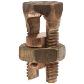
Figure 5: Split bolt
The bare wires are placed through the space between the two bolts, after which the nut is tightened to ensure a sound joint.
Making straight or branch Joints for steel wired armor cables
Required:
- Connectors Mechanical or crimp
- Copper mesh tape
- Constant force springs to hold the wire armor and copper mesh tape
- Standard PVC/Vinyl tape: provide a mechanical barrier between the over sheath layer and the armor layer.
Preparing the cable
- Remove the oversheath and the wire-armor
- Separate the wire armor and bend the wires away from the cable, place the support ring under the armor at each side of the joint.
- Cut back the cable insulation.
- Remove the insulation from each of the conductors
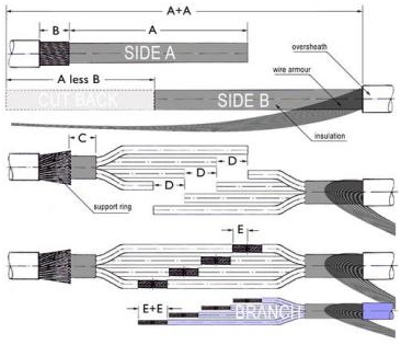
Figure 6: Preparation or a three core armored cable | image: gtgengineering
Crimp and insulate each cable
Once the cable is ready, connect each end of the three conductors to a suitable mechanical connector or the crimp. Tightly fix the matching connectors and test the connection.
Tape the crimped connectors, wrap around and extend to cover at least 25mm of the cable insulation of the conductor entering the connectors
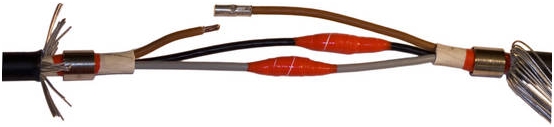
Figure 7: Tapped, crimped connectors on individual cables | image: gtgengineering
Bind the cables
Bind the wires tightly and then tape them together. When insulating both individual cables and the whole bunch, fill in the voids to create an even taper end to end.
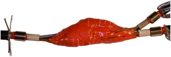
Figure 8: Wires taped together | image: gtgengineering
Restore Armor and apply mesh tape
- Tightly wrap the cable from armor to armor while applying adequate tension around the insulation.
- Join the wire armor from one end to the other end and cut excess wire to the correct length. Ensure the armor spread evenly over the entire joint.
- Wrap the cable with the mesh tape and then use the standard vinyl/PVC tape to wrap over the mesh to provide a mechanical barrier against stray wire ends. For the branch joint, bring both the main and branch cables together before wrapping.
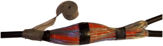
Figure 9: Wrapping the cable with mesh tape | image: gtgengineering
Next, use standard vinyl or PVC tape to wrap over the constant force springs placed over the under-armor rings. The tape provides a barrier against sharp edges.
Re-establish the over sheath
- Use a self fusing tape to wrap over the cable and establish the outer sheath. Start in the center and apply one layer of tape to one end, wrapping over the jacket with for at least 25 mm. Apply the tape from the end towards the center so that you have two layers on each side.
- For branch joints, wrap over the insulation for both the main and the branch cable, by at least 50mm. bring the two together and filling in with the insulating putty from both sides. Do this up to 25 mm away from the place where the branch and the main cables are joined.
- Put the two cables together and bind the main and branch tightly over the filling. Finally, wrap the crotch while pulling the branch away from the main cable.
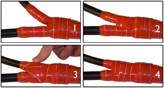
Figure 10: Restoring the over-sheath on a branch joint | image: gtgengineering
Summary
There are a variety of cable jointing techniques. The joints can made through twisting the wires, or using mechanical connectors such as crimps. A good joint should be electrically and mechanically stable, reliable and safe regardless of the method used.
The connectors enable one to easily make reliable and safe connections for a wide range of applications and voltages. After making any joint, other than overhead cables, the insulation, armor, and outer sheath should be restored depending on the type of the cable.
And finally, by using the proper tools and techniques, it is possible to make any type of an electrical cable joint without affecting the performance and safety of the cabling system.
Is it any way harmful to have a joint in AC wires Eg the room length is 40 ft and one cable is of 30 ft and extension of 10 ft is required will this joint create any problem ?