 Hi everybody, it’s Steven Mill.
Last time, I’ve read the article about Reverse power relay basics published in this blog. It was very interesting and well-written so I thought I would give my contribution too about this topic.
I chose to write about selecting a reverse power relay and I hope it will help you all!
The reverse power relays provide a means of protecting generators connected in parallel with other generators or utility power systems. The relay monitors the power from the generator and trips when a preset value is exceeded, hence preventing the generator from motoring. The tripping activates the circuit breaker which in turn de-energizes the circuit that may otherwise feed power to the generator.
A time delay is included so to prevent the false tripping due to transients associated with synchronization or other momentarily disturbances. Most of the relays have adjustable settings for both the sensitivity and the time delay.
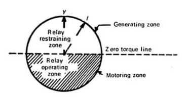
Figure 1: Reverse power relay operating characteristics | image: yourelectrichome.blogspot.com
Selecting a reverse power relay:
Below are some of the factors to consider when selecting the reverse power relay:
Sensitivity of the Reverse power relay
This specifies the power setting at which the tripping mechanism should activate. Typical settings for the trip point are between 2 and 20 percent and selected according to application.
Most of the reverse power relays have an adjustable setting to accommodate a wide range of applications.
When selecting the relay, it is important to consider the type of system being protected and ensure the relay covers this range. The sensitivity varies from one application to the other and diesel engines require a setting of between 8 and 15 percent, while the turbine power movers require a lower setting of between 2 and 6 percent.
Time delay in reverse power relays
This is the time it takes the relay to disconnect the power once the preset condition is met. This should be adjustable to allow the selection of the optimum point and prevent false tripping. For example, a 5 second delay is used in systems to avoid the protective system from tripping during synchronization.
Some relays are instantaneous whiles others have inbuilt time delay mechanisms. However, the time delay option can be incorporated into the instantaneous device.
Typical delays are between the instant at zero seconds to about 20 seconds.
Number of Phases
This depends on the type of the generator, and power system. There are both single phase and three phase reverse power relays to suit any type of an installation. The three phase relay are available either as 3 phase 4 wire relays, or a 3 phase 3 wire relays.
Power supply for the reverse power relay
The relay operates to activate a protection system such as a circuit breaker. For this to happen, it makes or breaks the contacts depending on whether they are normally open or closed. The relays can operate in either de-energize or energize mode. Either way, it requires power to supply the coils. The self powered relays have the advantage of being simpler and requiring no auxiliary power supply which can lead to malfunction when unavailable or low in the case of batteries.
Nominal voltage and current
The relay should be able to operate with the system voltage and current. Some of the typical nominal voltage ratings are; 110, 230, 277, 380, 415 and 480 volts, and 2, 4, 6, 8 and 10 A or 5 A nominal current.
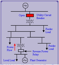
Figure 2: Reverse power protection | image: nptel.ac.in
Frequency of operation
Determine the frequency of the system to be protected. Typical frequencies are 50, 60 and 400Hz.
Operational environment
The device should be able to operate in a wide variety of temperatures typically between 0 and 60 degrees Celsius. In addition, the relay should be able to withstand storage temperatures of between 10 and 70 degrees Celsius.
Standards
Must conform to international standards such as- IEC 144 / BS 5420 / VDE/VDI 0435 / IEC 947 / EN60947
Relay output
Typical options:
- Single pole change over
- Double pole change-over
- Normally open or closed
Resetting the Reverse power relay
Once the parallel power is disconnected by the reverse power relay, it will require to be reset when the operation reverts back to normal. There are relays that are entirely manual and must be reset manually, while others are fully automatic requiring no operator intervention and others a hybrid with both manual and automatic options.
In most of the manual modes, the reset is done by pressing a push button or by disconnecting the supply voltage for a short period of about one second.
Mounting
The selection should be based on the existing control panel and mounting available. This can DIL rail mounting, wall, or panel mount.
Conclusion
To get desired reverse power protection, it is important to pay attention to various parameters of the relay to use. This should start by understanding the system to be protected and getting information of the voltage, current frequency and whether single or 3 phases. This helps in selecting the suitable relay with the ability to provide a repeatable and reliable operation, hence protecting the generator and other equipment in the system.
Thanks for reading, do not hesitate to leave your impressions or asking questions in the comments section!
Steven Mill.