
New article sent by one of our beloved visitors and member Yasser. This time, he chose to share an overview of Power Transmission Systems at MV and LV levels
If you too want to share writings with everybody, please send us a mail.
Introduction
Electrical power passes by many stages before it reaches our homes. The power generated at the utility can’t be directly to consumers due to many technical aspects such as:
- Generating voltage (11-22 KV).
- Distance between generating utility and consumers.
- Electricity must be at low voltage levels at the end user (110 – 220 V) for safety and devices size.
So as to the mentioned aspects we need transmission system to facilitate the process of feeding users with high quality and reliable electricity. Thus we have mainly three transmission systems from utility till the end user. These systems are:
- High Voltage Transmission System – above 220 KV (Over Head Transmission Lines)
- Medium Voltage Transmission system – less than 220 kV (OTHL and Underground Cables)
- Low Voltage Distribution system – less than 1 kV – near the user (Underground Cables)
All of these systems have different topologies in order to achieve some goals and stick to some standards to provide power quality, reliability, efficiency and safety for users and the equipment too. In the next paragraphs we will focus on the medium voltage transmission system (MVTS) showing some characteristics and topologies too.
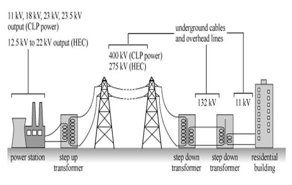
Figure 1: Schematic of Power Transmission and Distribution | image: hk-phy.org
Feeder systems typologies
Radial Feeder
The most common feeder system and it’s the simplest topology and the least expensive from both sides, construction and protection. But on the other hand it has a disadvantage which is, any fault in the system will lead to discontinuity of supply.
Radial system is shown in the following figure:
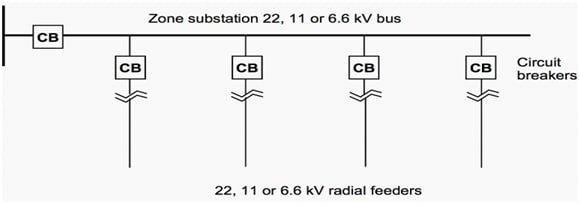
Figure 2: Typical Configuration of Radial Feeder | image: abbib.cloudapp.net
Parallel Feeder
This type of feeder system provides a higher level of reliability, safety and continuity of supply. To prevent power outage in case of faults, this system provide two main feeders from high to medium voltage so as to provide electric power in case of failure of any of the main feeders.
The cables follow different routes and protection equipment are doubled so, the capital cost is doubled. This feeding system is common where the reliability is required. The following figure shows a typical parallel feeder:

Figure 3: Typical Configuration of Parallel Feeder | image: electrical-engineering-portal.com
Ring Main
It introduces the same reliability as the parallel feeders as it’s the result of the growth of loads supplied by the parallel feeders. Cables are installed along with loads forming a ring shape. This system is commonly used in urban and industrial areas, as there are two routes for electric power to flow.
The following figure introduces a typical ring main feeder:
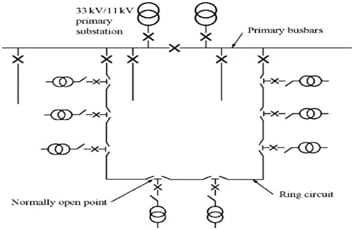
Figure 4: Typical Configuration of Ring Feeder | image: images.books24x7.com
Low Voltage distribution systems Feeders
We need to mention that, in medium voltage we talk about feeders between high voltage distribution system and low voltage distribution transformers so these circuits are the ones which supply distribution transformers. That’s why we care about reliability as any loss of power will lead to millions of people to be badly affected.
On the other hand, in low voltage distribution systems it comes between distribution transformers and your home appliances and sockets. LV distribution system is much simpler than medium voltage ones. And there are only two common methods:
- Loop system: In this system, the loop is made on feeder pillar level, each pillar have two or more incomers and one or more outgoings, so it’s fed by two or more sources, this system introduce high reliability and continuity of service.
- Radial system: it’s the same as in medium voltage, has the same disadvantages. It’s common when loads are big enough up to 100 KVA.
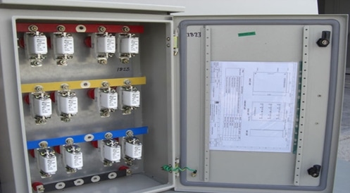
Figure 5: Feeder Pillar
Now after having an overview about topologies of electric distribution systems, we can imagine how many equipment are related to these systems, starting from current and voltage transformers, protection relays, powerful circuit breakers, switchgears and etc. which need much time to be covered.
Thank you for reading me,
Yasser.
Do you have more remarks to add after reading this essay? Commetn below!
Hi,It sounds good but what about Low Voltage distribution systems minimum watts??? and its features?
Inductor Coil Manufacturer in India | Medical Isolation Transformer in India
i see yours Electrical engineering Community and very nice so i need a job here please response my mail